Adjustable Exercise Machine

a technology of adjustable exercise machine and adjustable platform, which is applied in the direction of gymnastic exercise, cardiovascular exercise device, sport apparatus, etc., can solve the problems of accelerated muscle fatigue and increase in caloric energy consumption, and achieve the effect of shortening exercise time, shortening exercise time, and minimizing lateral and uplift movement of the movable platform

Active Publication Date: 2020-01-30
LAGREE TECH INC
View PDF0 Cites 18 Cited by
  • Summary
  • Abstract
  • Description
  • Claims
  • Application Information

AI Technical Summary

Benefits of technology

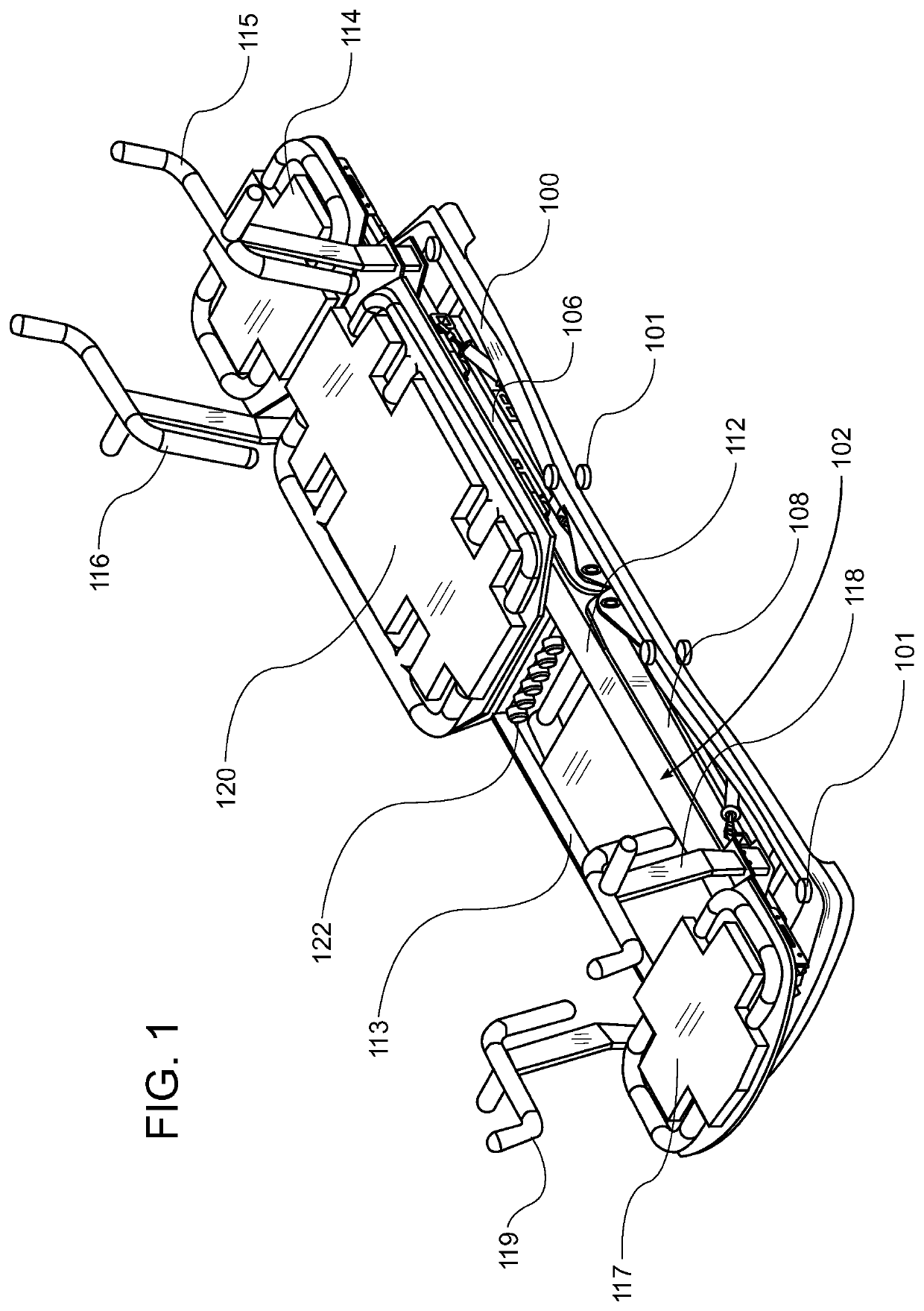
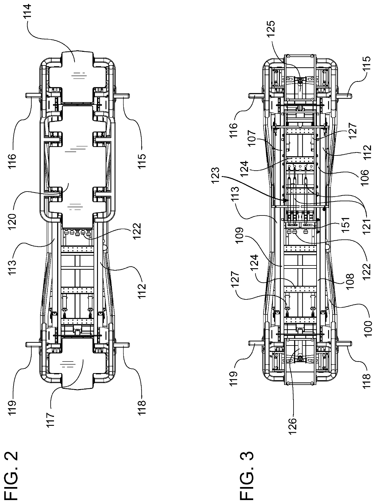
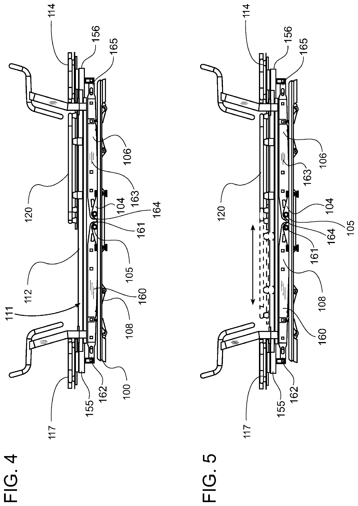
[0008]The exercise platforms are arranged in a common plane. In one position the platforms are substantially aligned in a horizontal plane. However, the distal ends of the machine may be selectively raised or lowered via the operation of cooperating components to incline the plane and add or subtract a variable portion of the exerciser's body weight to the resistance level provided by the exercise machine itself. This provides an efficient method for increasing the intensity of the exerciser's training and for shortening the exercise time needed for the exerciser to achieve desired results.
[0009]A plurality of novel trolley wheel assemblies support the movable platform on a pair of parallel rails and allow it to reciprocate between the stationary platforms. The rails include adjacent upper and lower sloped surfaces that are substantially perpendicular. The trolley wheel assemblies include a plurality of load wheels in rolling engagement with the upper sloped surfaces of the rails and at least one clamp wheel in rolling engagement with the lower sloped surfaces of the rails thereby minimizing lateral and uplift movement of the movable platform during exercise.
[0010]A plurality of travel limit decelerators are mounted on the rails at locations intended to engage the movable platform as it reaches its limits of travel on the rails. The travel limit decelerators function to rapidly and smoothly decelerate and bring the platform to a stop without damaging the platform or other machine components.

Problems solved by technology

Fitness trainers will appreciate that when exercisers lift all or a portion of their own body weight during a resistance exercise they experience an increase in caloric energy consumption and accelerated muscle fatigue.

Method used


Image

  • Adjustable Exercise Machine
  • Adjustable Exercise Machine
  • Adjustable Exercise Machine

Examples


Embodiment Construction

[0046]Various aspects of specific embodiments are disclosed in the following description and related drawings. Alternate embodiments may be devised without departing from the spirit or the scope of the present disclosure. Additionally, well-known elements of exemplary embodiments will not be described in detail or will be omitted so as not to obscure relevant details. Further, to facilitate an understanding of the description, a discussion of several terms used herein follows.

[0047]The word “exemplary” is used herein to mean “serving as an example, instance, or illustration.” Any embodiment described herein as “exemplary” is not necessarily to be construed as preferred or advantageous over other embodiments. Likewise, the term “embodiments” is not exhaustive and does not require that all embodiments include the discussed feature, advantage or mode of operation.

[0048]The phrase “linear actuator” is used herein to mean a device used to create linear motion by means of moving an extens...


PUM


Abstract

An adjustable exercise machine for performing resistance exercises comprises a base and an upper frame including front and back end stationary exercise platforms, and a movable exercise platform that reciprocates between the stationary platforms. A plurality of biasing members is selectable by an exerciser via selector knobs to generate a bias force against the movable platform. A plurality of pivotable lift supports are connected between the base and the upper frame. Front and back actuators are connected between the base and the lift supports by lifting yokes to selectively raise and lower the front and back ends of the machine. The movable platform may be connected to move along the exercise machine by trolley wheel assemblies. A plurality of travel limit decelerators mounted on the rails engage and rapidly decelerates the movable platform as it reaches its limits of travel on the rails.

Description

CROSS REFERENCE TO RELATED APPLICATIONS[0001]I hereby claim benefit under Title 35, United States Code, Section 119(e) of U.S. provisional patent application Ser. No. 62 / 703,062 filed Jul. 25, 2018. The 62 / 703,062 application is currently pending. The 62 / 703,062 application is hereby incorporated by reference into this application.STATEMENT REGARDING FEDERALLY SPONSORED RESEARCH OR DEVELOPMENT[0002]Not applicable to this application.BACKGROUNDField[0003]Example embodiments in general relate to the field of fitness training devices and exercise machines. More specifically, example embodiments relate to an exercise machine comprising a plurality of exercise platforms and supported by a plurality of repositionable arms, a plurality of actuators, and a plurality of shock absorbers operable to reposition the exercise platforms relative to a substantially horizontal axis.Related Art[0004]Any discussion of the related art throughout the specification should in no way be considered as an ad...

Claims


Application Information

Patent Timeline
Patent Type & Authority Applications(United States)
IPC IPC(8): A63B21/068A63B22/20A63B21/00A63B71/00A63B21/04
CPCA63B2225/09A63B21/4033A63B71/0054A63B21/068A63B21/00069A63B2071/0063A63B2071/0072A63B21/0428A63B21/4035A63B22/208A63B2225/093A63B2225/10A63B21/0083A63B2208/0252A63B21/4031A63B21/4047A63B21/4045
Inventor LAGREE, SEBASTIEN ANTHONY LOUISHAMILTON, JOHN C.
Owner LAGREE TECH INC
Why Eureka
Try Eureka