Generating a source point of shear waves for shear wave elasticity imaging

a source point and shear wave technology, applied in the field of shear wave elasticity imaging, can solve the problems of narrow field of view in obtained images, safety issues, and displacement of objects under study

Inactive Publication Date: 2020-02-06
MAKKIABADI BAHADOR
View PDF0 Cites 2 Cited by
  • Summary
  • Abstract
  • Description
  • Claims
  • Application Information

AI Technical Summary

Problems solved by technology

SWs may be generated as a result of ARF and may cause displacements inside an object under study.
However, focusing high power ultrasound beams inside objects may cause safety issues such as damaging a region under study.
In addition, ARF may provide one single focal point which may cause displacements inside of a limited region of an object, resulting in a narrow field of view in obtained images.
Simultane...

Method used


Image

  • Generating a source point of shear waves for shear wave elasticity imaging
  • Generating a source point of shear waves for shear wave elasticity imaging
  • Generating a source point of shear waves for shear wave elasticity imaging

Examples


example 1

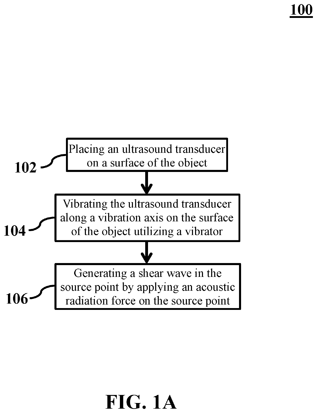
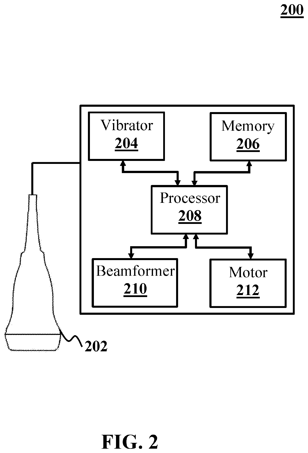
[0072]In this example, propagation of shear waves generated by an ARF at a single focal point is illustrated. The ARF is generated by an exemplary SWEI system (analogous to system 200). The SWEI system includes an ultrasound transducer (analogous to ultrasound transducer 202), a vibrator (analogous to vibrator 204), a memory (analogous to memory 206), a processor (analogous to processor 208), a beamformer (analogous to beamformer 210), and a motor (analogous to motor 212). The ultrasound transducer includes an annular array transducer (analogous to AAT 318). The ultrasound transducer applies an acoustic radiation force (analogous to acoustic radiation force 312) to an exemplary object (analogous to object 304). The value of displacements are obtained by computer simulations. The computer simulations are based on a forward problem of displacement measurement from an acoustic wave equation. Finite difference method is utilized for solving the acoustic wave equation.

[0073]FIG. 5 shows ...

example 2

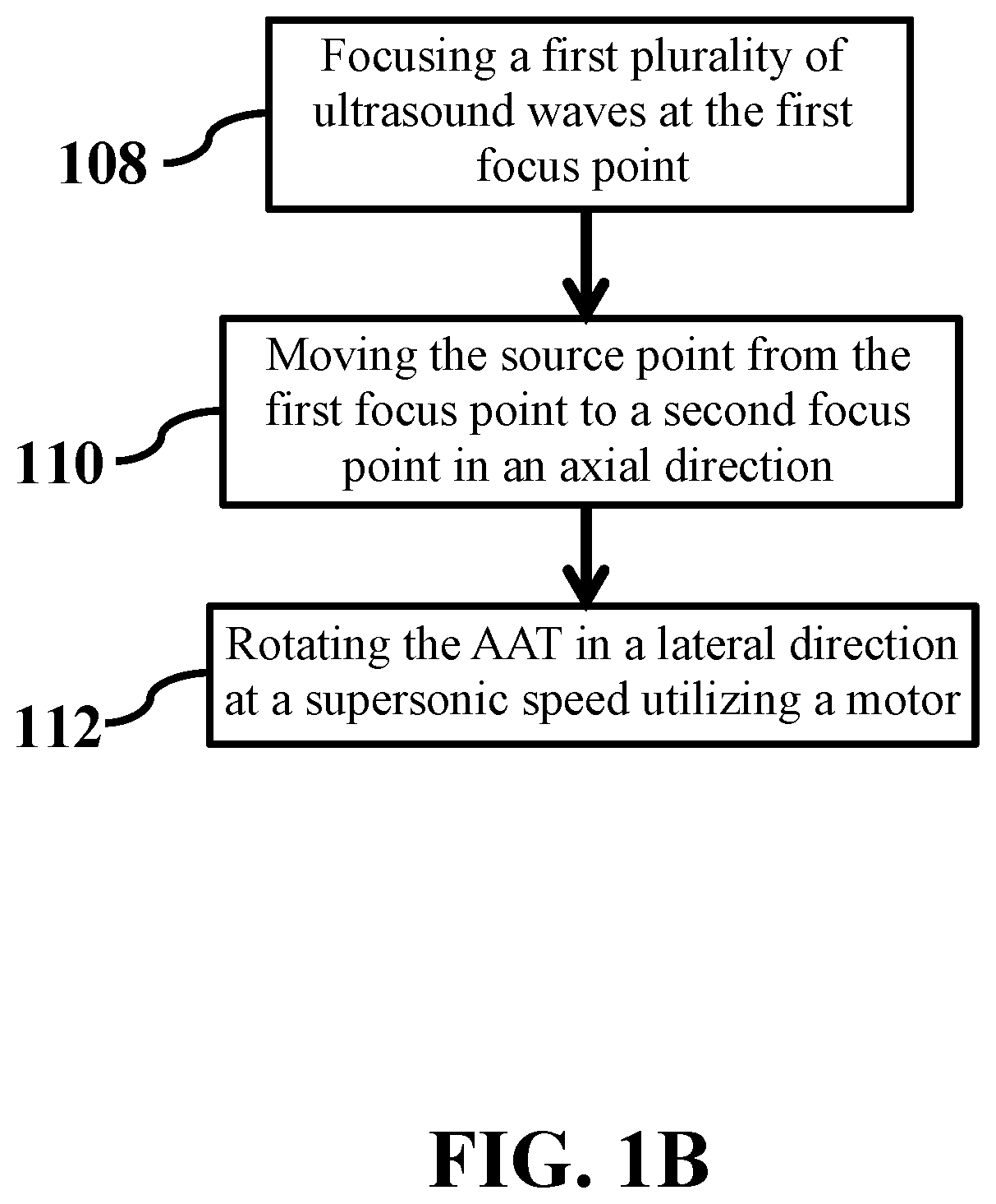
[0074]In this example, propagation of shear waves generated by ARFs at six focal points in an axial direction is illustrated. An exemplary SWEI system, similar to the SWEI system of EXAMPLE 1, is implemented in which an ultrasound transducer applies ARFs at six focal points. FIG. 6 shows propagation of shear waves generated by ARFs at six single focal points in an axial direction, consistent with one or more exemplary embodiments of the present disclosure. The focal points are arranged equally apart in an axial direction (analogous to axial direction 328) at a focal distance (analogous to focal distance 317) of about 35 mm to about 50 mm. The ultrasound transducer applies ARF at focal points at a supersonic speed. Subfigures (a) to (f) show propagation of generated shear waves and associated Mach cones at different moments. As FIG. 6 shows, Mach cones are generated in an axial direction and propagate in a lateral direction (analogous to lateral direction 340) through time. It can be...

example 3

[0075]In this example, propagation of shear waves generated by ARFs at six focal points at a high supersonic speed is illustrated. An exemplary SWEI system, similar to the SWEI system of EXAMPLE 2, is implemented in which an ultrasound transducer applies ARFs at six focal points at a supersonic speed twice as that of EXAMPLE 2. FIG. 7 shows propagation of shear waves generated by ARFs at a high supersonic speed, consistent with one or more exemplary embodiments of the present disclosure. Subfigures (a) to (f) show propagation of generated shear waves and associated Mach cones at different moments. As it can be observed, a Mach angle (analogous to Mach angle 334) reduces compared to that of FIG. 5 due to an increase in speed of generation of shear waves.


PUM


Abstract

A method for generating a source point of shear waves for shear-wave elasticity imaging (SWEI) of an object. The method includes placing an ultrasound transducer on a surface of the object, vibrating the ultrasound transducer along a vibration axis utilizing a vibrator when the ultrasound transducer is placed on the surface of the object, and generating a shear wave in the source point by applying an acoustic radiation force on the source point. Applying the acoustic radiation force includes focusing an ultrasonic beam of the ultrasound transducer at a first focus point. The first focus point is located at the source point. The acoustic radiation force is applied simultaneously with vibrating the ultrasound transducer.

Description

CROSS-REFERENCE TO RELATED APPLICATION[0001]This application claims the benefit of priority from pending U.S. Provisional Patent Application Ser. No. 62 / 745,298, filed on Oct. 13, 2018, and entitled “ANNULAR ARRAYS IN TRANSIENT ELASTOGRAPHY,” which is incorporated herein by reference in its entirety.TECHNICAL FIELD[0002]The present disclosure generally relates to elastography, and particularly, to shear-wave elasticity imagingBACKGROUND[0003]Shear wave (SW) elastography is used for imaging soft objects by inducing acoustic SWs into a body and scanning echoes of transmitted waves. Since velocity of SWs may depend on elasticity of propagation media (i.e., intended objects for imaging), elasticity (or stiffness) level of objects may be inferred by scanning velocity of SWs.[0004]Acoustic radiation force (ARF) is a prominent way of generating acoustic SWs. ARF may create longitudinal waves using focused ultrasound beams inside object media. SWs may be generated as a result of ARF and may...

Claims


Application Information

Patent Timeline
IPC IPC(8): A61B8/08A61B8/00G01S7/52
CPCG01S7/52085A61B8/4461A61B8/4494A61B8/485G01S7/52042A61B8/5207A61B8/54G01S15/8922
Inventor MAKKIABADI, BAHADORMARDI, ZAHRABEITOLLAHI, MAHDIMEIMANI, NAJMEHMANUCHEHRI, MOHAMMAD SAJAD
Owner MAKKIABADI BAHADOR
Why Eureka
Try Eureka