Assembly for Converting a Wheel Drive Harvester to Track Drive

a technology of track drive and harvester, which is applied in the direction of endless track vehicles, vehicles, transportation and packaging, etc., can solve the problems of loss of harvestable cotton, excessive wet and muddy field of cotton ready to be harvested, undesired choice, etc., to facilitate independent pivoting of track chassis, reduce stress, and support the weight of the harvester

Active Publication Date: 2020-02-06
SWISHER DON E +1
View PDF0 Cites 0 Cited by
  • Summary
  • Abstract
  • Description
  • Claims
  • Application Information

AI Technical Summary

Benefits of technology

[0011]Horizontal extension arm components may preferably extend leftwardly and rightwardly from the distal ends of the “U” bracket's left and right “U” arms. Such horizontal extension arms preferably support eyed mounting plates to which the harvester's left and right hub gears (previously de-installed from their forward tire supporting and driving positions) may be attached. Accordingly, the horizontal extension arms rigidly support the track assembly's drive sprockets in a manner similar to the support of the formerly attached drive wheels. The provision of pivoting left and right “Y” bracket mounts for the track chassis support advantageously reduces stress exerted against the reinstalled hub gears which connect with and rotatably drive the tracks' drive sprockets. To facilitate independent pivoting motion of the track chassis with respect to the rotation axis of the drive sprocket, mechanical linkages between the drive sprocket and the chassis are preferably released.
[0012]As indicated above, a novel and useful aspect of the inventive assembly is its provision of track chassis engaging and supporting “Y” brackets which are pivotally mounted at below the distal ends of the “U” bracket's “U” arms. Such “Y” bracket pivot mounts allow the “U” bracket to dually support left and right track drive assemblies at both their drive sprockets and at their idler wheel supporting chassis. Such “Y” configured mounting structures advantageously allow the “U” bracket's support of the track's drive sprockets to be dedicated to rotatably driving those sprockets. While the rotary power is translated to the drive sprockets via interposed hub gears, the major support of the weight of the harvester is provided via the additionally provided track chassis supporting “Y” brackets. The retro-fitted track assemblies support the harvester without unduly stressing the sprocket rotating hub gears by allowing the weight supporting function of the hub gears to be bypassed and transferred to the underlying pivoting track support “Y” brackets.
[0013]In use of the instant inventive assembly, an operator of a cotton harvester who needs to use the harvester upon a wet field may easily and conveniently remove the harvester's drive wheels. Thereafter, the harvester's hub gears may be de-installed. Thereafter, the inventive “U” bracket may be conveniently bolted in place with the forward ends of the left and right setback arms being attached in a manner identical to the formerly attached hub gears. Thereafter, left and right track assemblies may be mounted upon the left and right horizontal extension arms with column portions of the track chassis supporting “Y” brackets attaching to the lower ends of the left and right downward extension arms, and with track drive sprockets attached (via interposed hub gears)to mounting plates at the laterally outer ends of the left and right horizontal extension arms. Following such installation, the harvester may be operated in a conventional fashion, but with additional floatation provided by the track assemblies.
[0014]During such conventional operation, the weight of the harvester is borne by the pivoting track support “Y” brackets, advantageously relieving stresses which may otherwise translate from the tracks to the “U” bracket via the sprocket driving hub gears.

Problems solved by technology

In many circumstances, a field of cotton which is ready to be harvested may be excessively wet and muddy.
In such circumstances, a cotton farmer having available only a conventional wheel and tire driven cotton harvester may be undesirably forced to choose between driving the harvester over the muddy field and delaying the cotton harvest until the field dries.
Such choice often imposes an undesirable dilemma, subjecting the cotton farmer to alternative risks of a harvester stuck in the mud in the cotton field, and loss of harvestable cotton due to a delaying the harvest for field drying.
Such undesirable wet field related cotton harvesting dilemmas give rise to the desirability of a mechanical capacity within a cotton harvester for alternatively including and utilizing a conventional wheel and tire drive system (for dry field harvesting) and a track drive system (for wet field harvesting).
However, commonly known and configured cotton harvesters which include a conventional wheel and tire front drive assemblies often position their left and right drive wheels so far forwardly in relation to the row unit that an acceptably large track drive assemblies cannot be alternatively mounted at the former or de-installed locations of the drive wheels.
Also, a conversion of a wheel drive harvester to track drive often solely mounts the track drive at or upon the rotary axis of the track's drive sprocket, resulting in undue stresses imposed upon a hub gear or final drive mounted to the harvester's chassis at that axial location.

Method used


Image

  • Assembly for Converting a Wheel Drive Harvester to Track Drive
  • Assembly for Converting a Wheel Drive Harvester to Track Drive
  • Assembly for Converting a Wheel Drive Harvester to Track Drive

Examples


Embodiment Construction

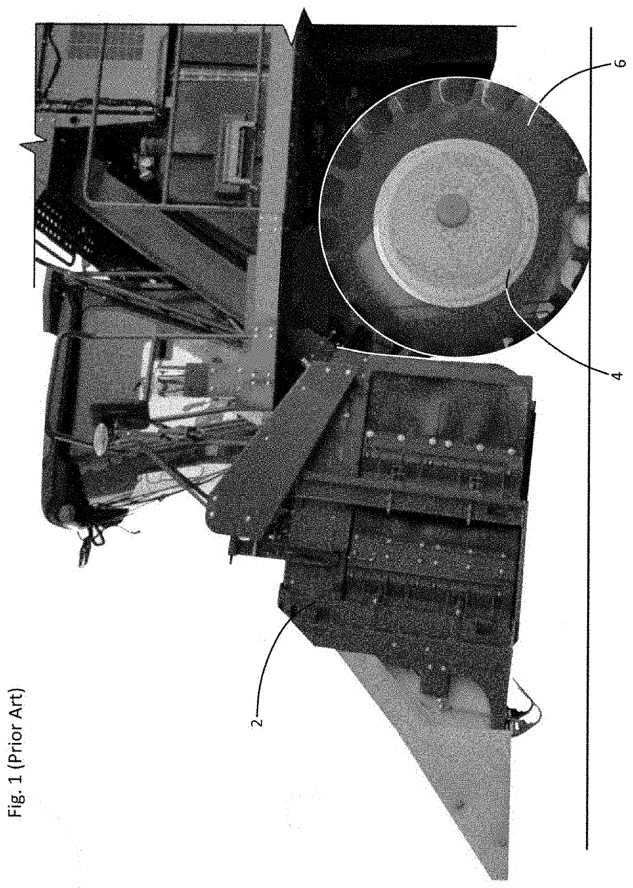
[0027]Referring now to the drawings and in particular to Drawing FIG. 1, a prior art cotton picking and processing harvester has a laterally extending front row unit 2. Functions of picking and processing cotton are performed by the row unit 2 through the action of barbed rotary spindles within the row unit. Cotton fiber which is mechanically doffed from the spindles is rearwardly blown and is formed within the rear of the harvester into a brick or bale module.

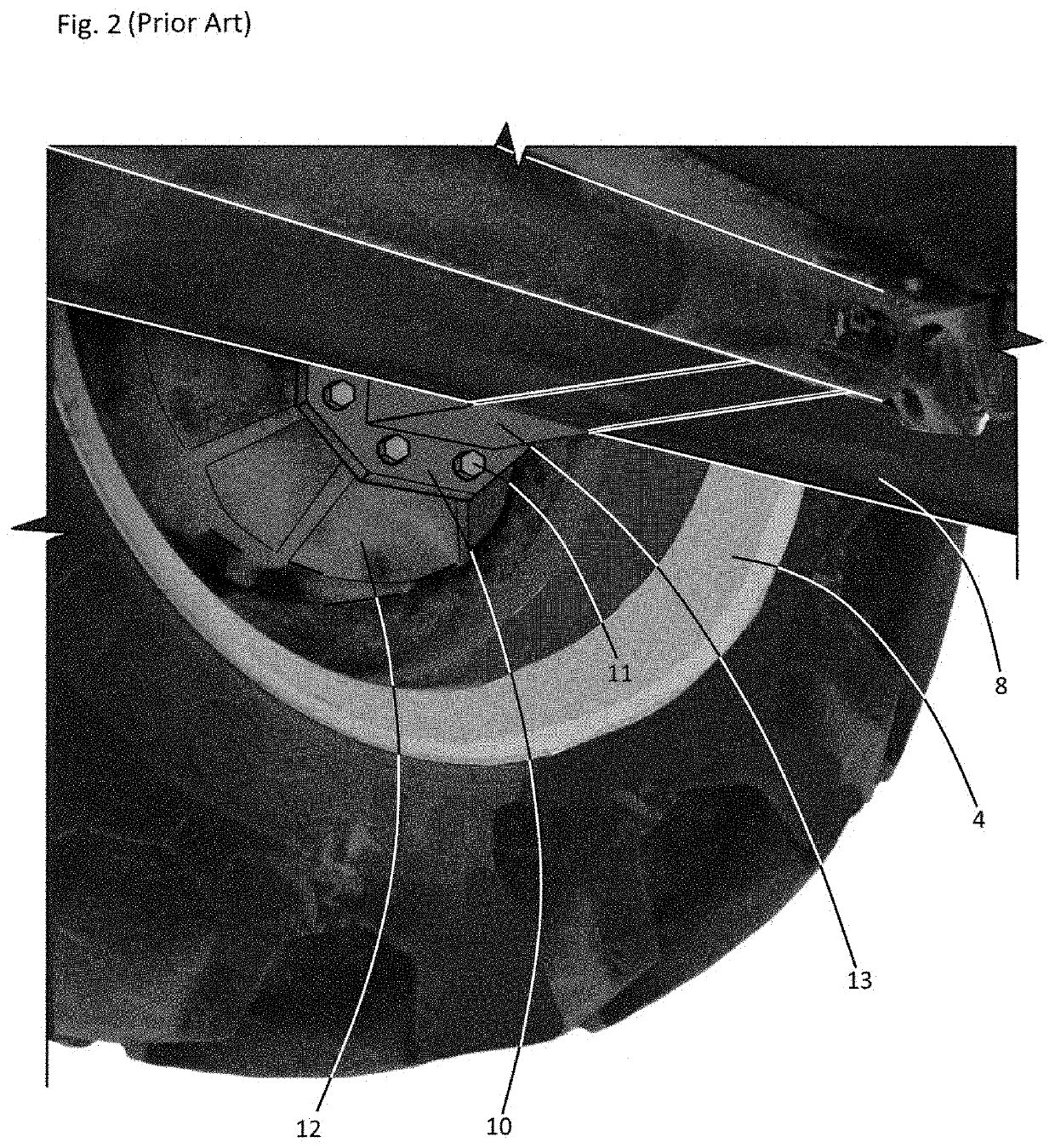
[0028]Left and right drive wheels 4 having mounted pneumatic tires 6 are conventionally mounted for driving the cotton harvester forwardly over cotton fields. Looking simultaneously to FIGS. 1 and 2, each of the harvester's left and right drive wheel and tire 4,6 combinations is rigidly supported upon the vehicle's chassis or undercarriage 8 by means of a rigid mounting arm 13 to which a mounting plate 10 is rigidly attached. A hub gear or final drive assembly 12 including interior planetary gears (not depicted within views) i...


PUM


Abstract

A retrofit assembly for conversion of a wheel driven vehicle to track drive, the vehicle having an undercarriage and left and right final drive mounts, the assembly incorporating left and right setback arms attached to and extending rearwardly from the vehicle's left and right final drive mounts; a “U” bracket having left and right “U” arms, the “U” bracket being fitted for laterally spanning the vehicle's undercarriage, wherein distal ends of the left and right “U” arms are fixedly attached to rearward ends of the left and right setback arms, and wherein forward ends of the setback arms are fixedly attached to the vehicle's left and right final drive mounts; left and right final drives respectively fixedly attached to the rearward ends of the left and right setback arms; and left and right sprocket driven tracks, wherein the track's sprockets are fixedly attached to the left and right final drives.

Description

FIELD OF THE INVENTION[0001]This invention relates to self-propelled agricultural harvester vehicles and other types of heavy self-propelled vehicles. More particularly, this invention relates to apparatus and assemblies which are adapted for converting such vehicles from wheel and tire drive to continuous loop track drive.BACKGROUND OF THE INVENTION[0002]Commonly known and configured spindle type cotton harvesters have a forward cotton bole picking and processing row unit, and include left and right drive wheels positioned immediately rearwardly from the row unit. In many circumstances, a field of cotton which is ready to be harvested may be excessively wet and muddy. In such circumstances, a cotton farmer having available only a conventional wheel and tire driven cotton harvester may be undesirably forced to choose between driving the harvester over the muddy field and delaying the cotton harvest until the field dries. Such choice often imposes an undesirable dilemma, subjecting t...

Claims


Application Information

Patent Timeline
Patent Type & Authority Applications(United States)
IPC IPC(8): B62D55/04
CPCB62D55/04B62D55/125B62D55/084
Inventor SWISHER, DON EJORDAN, GLYN
Owner SWISHER DON E
Why Eureka
Try Eureka