Feeder module

a technology of feeder module and feeder plate, which is applied in the direction of thin material processing, article separation, electrical apparatus, etc., can solve the problems of evident waste of processing time and lowered processing efficiency, and achieve the effect of increasing the processing efficiency of multi-functional products

Inactive Publication Date: 2020-02-06
KINPO ELECTRONICS
View PDF3 Cites 2 Cited by
  • Summary
  • Abstract
  • Description
  • Claims
  • Application Information

AI Technical Summary

Benefits of technology

[0008]To sum up, the feeder module identifies the size specification of the document placed at the tray through the at least two first sensors and the clamping member disposed in the second axial direction. That is, the clamping member has at least two shielding pieces moving in the second axial direction along with the clamping member. The at least two first sensors are located on the moving paths of the at least two shielding pieces so as to be shielded or not through the at least two shielding pieces, such that the at least two first sensors generate different sensing states. In this way, the control unit can determine the width of the document through the sensing states of the at least two first sensors. The width is parallel to the second axial direction. Therefore, before the multi-function product processes the document, that is, after the document is clamped by the clamping member, the multi-function product can obtain the size specification of the document. In this way, the multi-function product can accordingly perform processing corresponding to the required data volume, and that processing efficiency of the multi-function product can be effectively increased.

Problems solved by technology

Nevertheless, as variety of sizes of paper grows, if the largest size of paper is still used to act as the basis, the processing time is evidently wasted, so that processing efficiency is lowered.
Accordingly, how a multi-function product can more effectively sense the sizes of paper through a proper structure and element arrangement so that the multi-function product can obtain the sizes of paper in advance, so as to perform data transmission based on the corresponding sizes to enhance processing efficiency is an important issue in this field.

Method used


Image

  • Feeder module
  • Feeder module
  • Feeder module

Examples


Embodiment Construction

[0020]Descriptions of the disclosure are given with reference to the exemplary embodiments illustrated by the accompanying drawings. Wherever possible, the same reference numbers are used in the drawings and the description to refer to the same or like parts.

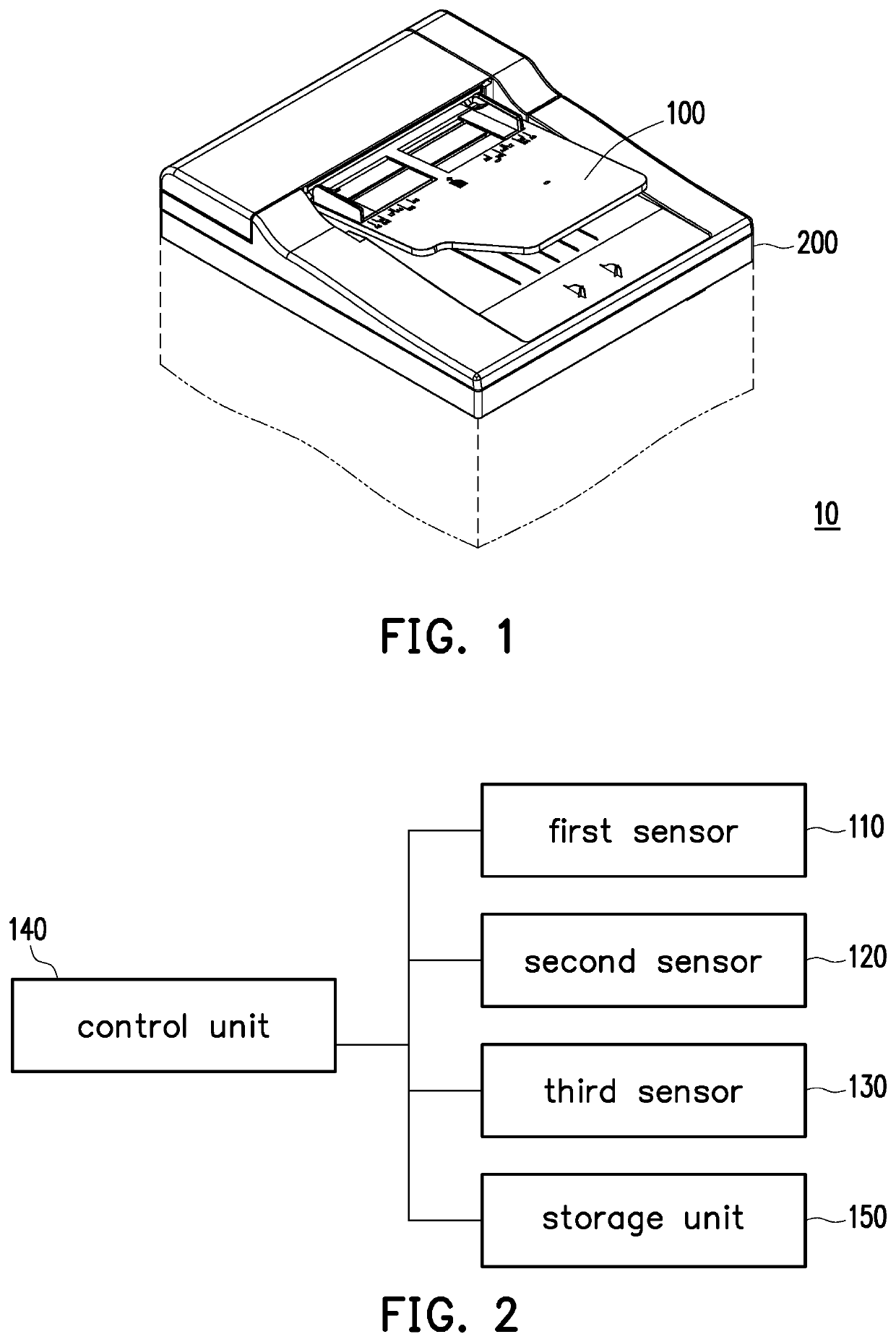
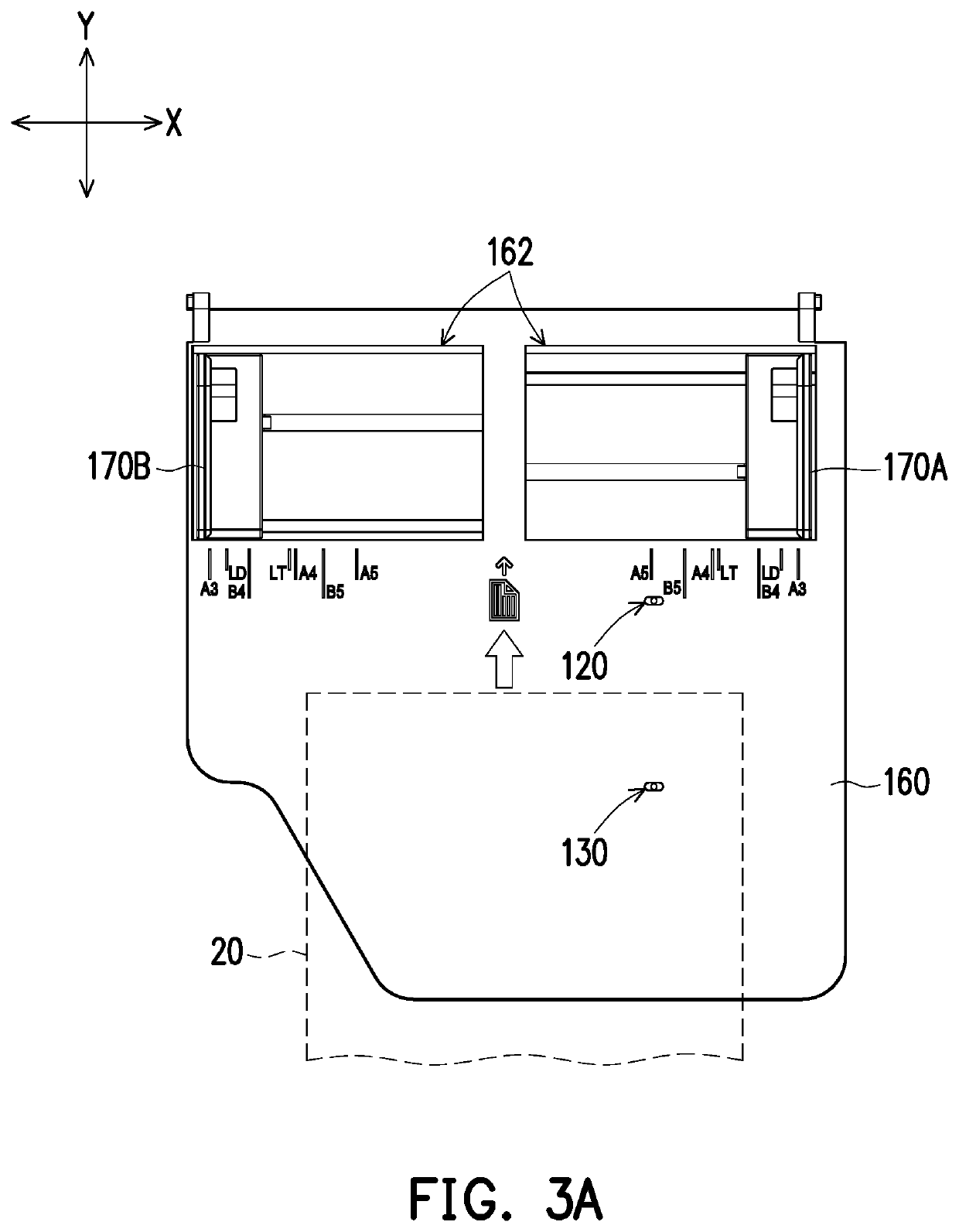
[0021]FIG. 1 is a schematic view of a multi-function product. FIG. 2 is a diagram illustrating electrical connection relations of part of members of the multi-function product. FIG. 3A is a top view of a feeder module. With reference to FIG. 1, FIG. 2, and FIG. 3A together, in this embodiment, a multi-function product / printer / peripheral (MFP) 10 is a known automatic office apparatus which incorporates multiple functions, such as copying, faxing, scanning, printing, etc. The multi-function product 10 includes a machine base 200 and a feeder module 100 disposed thereon. A document 20 (i.e. a paper) is suitable for being placed on a tray 160 of the feeder module 100. The tray 160 has a first axial direction Y and a second axial dir...


PUM


Abstract

A feeder module for a multi-function product including a tray having a first axial direction and a second axial direction, at least two first sensors disposed at the tray in the second axial direction, a clamping member movably assembled to the tray in the second axial direction, and a control unit is provided. A document placed on the tray is driven to move into the multi-function product in the first axial direction. The clamping member has at least two shielding pieces moving in the second axial direction. The first sensors located on moving paths of the shielding pieces generate different sensing states according to whether the first sensors being shielded by the shielding pieces or not. A control unit electrically connected to the first sensors determines a width of the document according to the sensing states of the at least two first sensors.

Description

CROSS REFERENCE TO RELATED APPLICATION[0001]This application claims the priority benefit of China application serial no. 201810862258.0, filed on Aug. 1, 2018. The entirety of the above-mentioned patent application is hereby incorporated by reference herein and made a part of specification.BACKGROUNDTechnical Field[0002]The disclosure relates to a feeder module suited for a multi-function product.Description of Related Art[0003]Generally, in multi-function products (MFP) providing the paper feeding function, sizes of paper can not be identified by the multi-function products most of the time. That is, in an existing auto feeder module (Auto Document Feeder, ADF), the largest size of paper is used as the basis for data transmission actually.[0004]Nevertheless, as variety of sizes of paper grows, if the largest size of paper is still used to act as the basis, the processing time is evidently wasted, so that processing efficiency is lowered.[0005]Accordingly, how a multi-function produ...

Claims


Application Information

Patent Timeline
Patent Type & Authority Applications(United States)
IPC IPC(8): B65H5/06H04N1/00
CPCH04N1/0057B65H2511/11B65H2801/06B65H2402/44B65H2801/39B65H2553/41B65H2511/12B65H2403/40B65H5/06H04N1/00572H04N1/00795B65H1/04B65H2511/20B65H2220/01B65H2220/02
Inventor CHIANG, SHIH-HISSUNG, HUNG-HUAN
Owner KINPO ELECTRONICS
Why Eureka
Try Eureka