Joint Arthrodesis System

a joint arthrodesis and joint technology, applied in the field of joint arthrodesis systems, can solve the problems of inability to use the same fusion device with both the posterior and the lateral approaches, and the possibility of errors or patient injuries increasing,

Active Publication Date: 2020-02-13
BLUE SKY TECHNOLOGIES LLC
View PDF61 Cites 3 Cited by
  • Summary
  • Abstract
  • Description
  • Claims
  • Application Information

AI Technical Summary

Benefits of technology

[0016]The more tools or instruments inserted into a surgical field, the greater the possibility of an error or patient injury may occur. Due to the simplicity of the current joint arthrodesis system, a number of surgical tools required and steps associated with performing prior state-of-the-art fusions can be eliminated. The arthrodesis procedures, among other uses, can be performed in the cervical spine, sacroiliac joint, ankle, hand or other similar joints.
[0019]Unlike other joint arthrodesis systems, the present system's joint arthrodesis implant includes a cutting edge and one or more rotatable cutters including one or more blades. Among other things, it is believed that the cutters can assist with the postoperative stabilization of the joint implant. In accordance with the current invention, rotation of a blade about 90 degrees allows the blade to extend beyond the joint implant's framework and penetrate adjacent cartilage and bone.
[0027]Still another aspect of the present invention is to provide edges on the cutting arms that can assist with the morselization of bone.

Problems solved by technology

The more tools or instruments inserted into a surgical field, the greater the possibility of an error or patient injury may occur.
Applicant's understanding is: there are fusion devices for use with either the posterior approach or the lateral approach, but the same fusion device is incapable for use with both the posterior and the lateral approaches.
Many of the current sacroiliac fusion procedures require the use of working cannulas, numerous broaches, rasps, drills and other devices that tend to complicate the surgical procedure.

Method used


Image

  • Joint Arthrodesis System
  • Joint Arthrodesis System
  • Joint Arthrodesis System

Examples


Embodiment Construction

[0044]Although the disclosure hereof is detailed to enable those skilled in the art to practice the invention, the embodiments published herein merely exemplify the present invention.

[0045]As used herein, with respect to the joint arthrodesis system's implant: 1) “anterior” of the joint implant means the side of the implant most distant from the surgeon and 2) “posterior or surgeon-facing side” of the joint implant means the side of the implant nearest the surgeon.

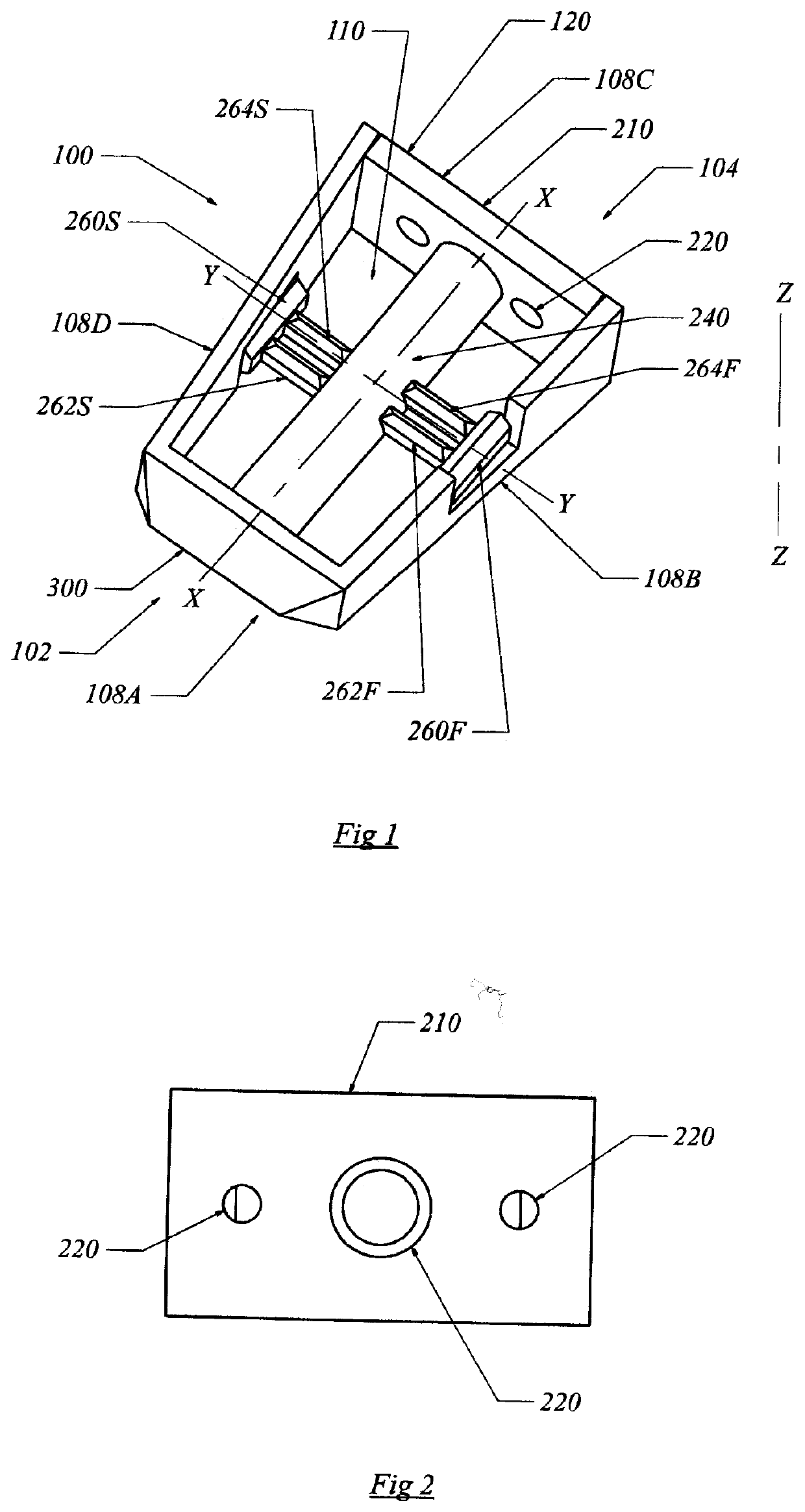
[0046]In the most general sense, the present invention is a joint arthrodesis system where an implant is surgically inserted into a joint space. The current implant can be useful for surgeries that can assist in stabilizing injured, deformed and or degenerative joints. Preferred embodiments of the current invention can be employed with ankle, cervical, hand, sacroiliac or other orthopaedic procedures. It appears that the present system is particularly useful for posterior cervical fusions and sacroiliac joint fusions. Howe...


PUM


Abstract

A joint arthrodesis system adapted for use in joint surgeries. Among other things, the joint implant has an anterior cutting edge and a rotatable cutter supported by a rotatable shaft.

Description

[0001]Applicant claims priority to PCT Application entitled—Joint Arthrodesis System—, Serial No. PCT / US2018 / 025785, filed Apr. 3, 2018 that claimed priority to US provisional Patent Application entitled—Joint Arthrodesis System—, Ser. No. 62 / 534,155, filed Jul. 18, 2017.BACKGROUND OF THE INVENTIONA. Field of the Invention[0002]The present invention is a joint arthrodesis system. Among other things, the implant of the current system has a cutting edge as well as a rotatable cutter.B. Description of the Previous Art[0003]Any discussion of references cited in this Description of the Previous Art merely summarizes the disclosures of the cited references and Applicant makes no admission that any cited reference or portion thereof is relevant prior art. Applicant reserves the right to challenge the accuracy, relevancy and veracity of the cited references.[0004]1) U.S. Pat. No. 6,770,096-Bolger, et al. discloses an interbody spinal stabilization cage and spinal stabilization method. Among...

Claims


Application Information

Patent Timeline
Patent Type & Authority Applications(United States)
IPC IPC(8): A61F2/44A61F2/46
CPCA61F2002/30593A61F2002/30845A61F2002/30266A61F2002/30364A61F2/447A61F2/4611A61F2/4455A61F2002/30158A61F2/42A61F2/4603A61F2/4606A61F2002/30179A61F2002/30538A61F2002/30579A61F2002/30622A61F2002/30995A61F2002/4627A61B17/8685A61F2002/30281A61F2002/30365A61F2002/30841A61F2002/30904A61B17/7002A61B17/7022A61B17/7032A61B17/7044A61B17/7053A61B17/7059A61B17/707A61B17/809A61F2002/4677A61B17/7071A61B17/1671A61B2017/00884A61F2/44A61F2/4405A61F2002/30736A61F2002/449A61F2310/00017A61F2310/00023
Inventor CASTRO, FRANK
Owner BLUE SKY TECHNOLOGIES LLC
Why Eureka
Try Eureka