Control system for work vehicle, method and work vehicle

a control system and work vehicle technology, applied in mechanical machines/dredgers, soil shifting machines/dredgers, constructions, etc., can solve the problems of difficult to perform digging work smoothly, the blade may rise suddenly, and the load applied to the blade may increase rapidly, so as to reduce the probability of slippage, improve work efficiency, and suppress slippage.

Active Publication Date: 2020-02-20
KOMATSU LTD
View PDF16 Cites 0 Cited by
  • Summary
  • Abstract
  • Description
  • Claims
  • Application Information

AI Technical Summary

Benefits of technology

The invention is a control system for a work vehicle that can automatically adjust the position of the blade to prevent excessive load on it and minimize the occurrence of shoe slips during digging. This system can improve the efficiency and quality of the finished work.

Problems solved by technology

Therefore, when digging a topography 300 with large undulations, the load applied to the blade may increase rapidly, causing the blade to rise suddenly.
If that happens, a very uneven topography will be formed, making it difficult to perform digging work smoothly.
Also, there is a concern that the topography being dug will be prone to becoming rough and the finish quality will suffer.
However, if the target value is not appropriate, a shoe slip will frequently occur.
In that case, it is difficult to perform digging work with high efficiency and high quality finish.

Method used


Image

  • Control system for work vehicle, method and work vehicle
  • Control system for work vehicle, method and work vehicle
  • Control system for work vehicle, method and work vehicle

Examples


Embodiment Construction

)

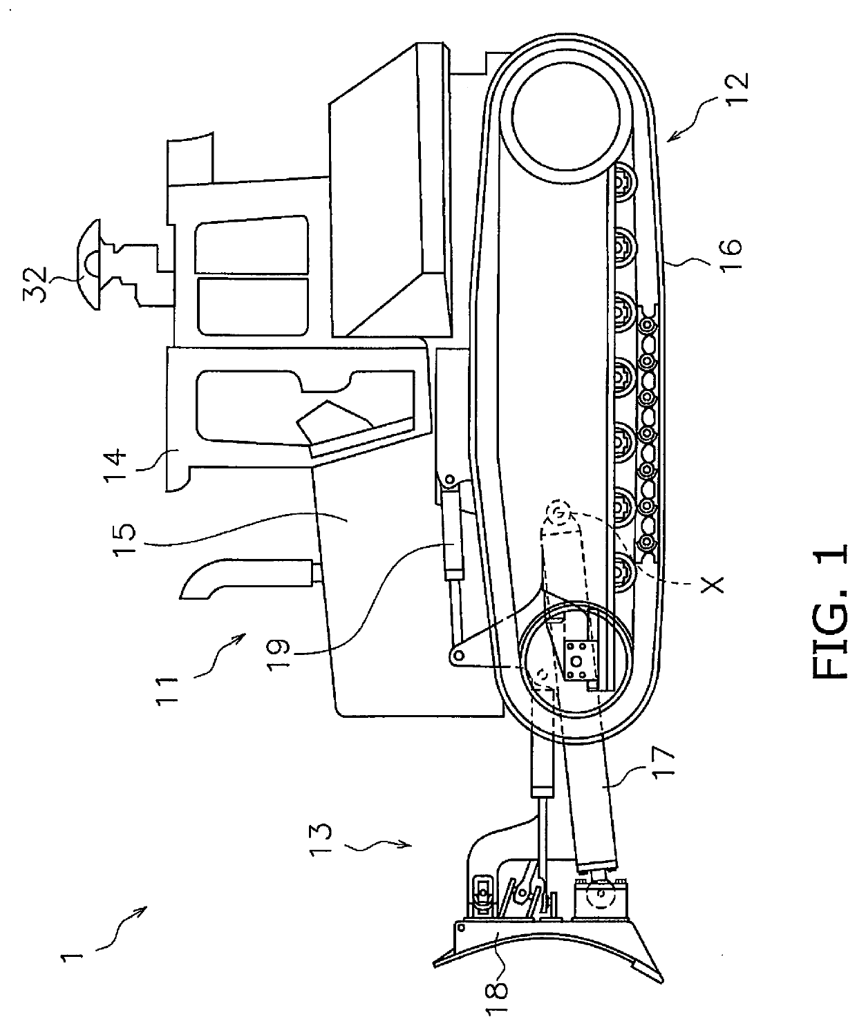
[0022]A work vehicle according to an embodiment will now be described with reference to the drawings. FIG. 1 is a side view of a work vehicle 1 according to an embodiment. The work vehicle 1 according to the present embodiment is a bulldozer. The work vehicle 1 includes a vehicle body 11, a travel device 12, and a work implement 13.

[0023]The vehicle body 11 includes an operating cabin 14 and an engine compartment 15. An operator's seat that is not illustrated is disposed inside the operating cabin 14. The engine compartment 15 is disposed in front of the operating cabin 14. The travel device 12 is attached to a bottom portion of the vehicle body 11. The travel device 12 includes a pair of right and left crawler belts 16. Only the left crawler belt 16 is illustrated in FIG. 1. The work vehicle 1 travels due to the rotation of the crawler belts 16. The travel of the work vehicle 1 may be either autonomous travel, semi-autonomous travel, or travel by an operation of an operator.

[0024]...


PUM


Abstract

A work vehicle includes a travel device and a work implement. A control system for the work vehicle includes a controller. The controller controls the work implement according to a predetermined target value. The controller determines whether a slip of the travel device has occurred during control of the work implement. The controller changes the target value according to a result of determination of the slip.

Description

CROSS-REFERENCE TO RELATED APPLICATIONS[0001]This application is a U.S. National stage application of International Application No. PCT / JP2018 / 017984, filed on May 9, 2018. This U.S. National stage application claims priority under 35 U.S.C. § 119(a) to Japanese Patent Application No. 2017-101364, filed in Japan on May 23, 2017, the entire contents of which are hereby incorporated herein by reference.BACKGROUNDField of the Invention[0002]The present invention relates to a control system for a work vehicle, a method, and a work vehicle.Background Information[0003]Conventionally, automatic control for automatically adjusting the position of a work implement has been proposed for work vehicles such as bulldozers or graders. For example, Japanese Patent Publication No. 5247939 discloses digging control. Under the digging control, the position of a blade is automatically adjusted such that the load applied to the blade coincides with a target load.SUMMARY[0004]With the conventional contr...

Claims


Application Information

Patent Timeline
IPC IPC(8): E02F9/26E02F3/84E02F3/76E02F9/20
CPCE02F9/262E02F9/265E02F3/7609E02F3/844E02F9/2041E02F3/7618E02F3/842E02F3/847E02F9/205E02F9/2037E02F9/2079
Inventor ISHIBASHI, EIJISHIMOJO, TAKAHIRO
Owner KOMATSU LTD
Why Eureka
Try Eureka