

LNG production system equipped with recondenser
a production system and recondenser technology, applied in cold treatment separation, liquefaction, solidification, etc., can solve the problems of requiring a large amount of energy to compress the bog, the total amount of lng produced cannot be transferred to the transport ship tank, and the inability to discharge bog into the atmospher
- Summary
- Abstract
- Description
- Claims
- Application Information
AI Technical Summary
Benefits of technology
Problems solved by technology
Method used
Image

Examples
embodiment 1
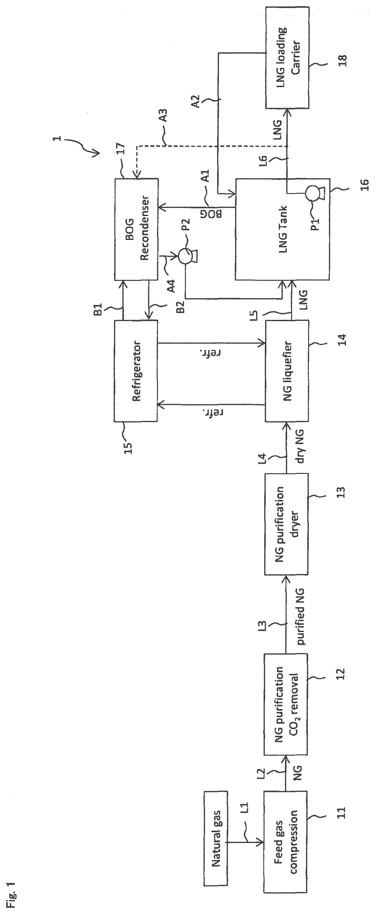
[0086]An LNG production system 1 of embodiment 1 will be described with reference to FIG. 1. The LNG production system 1 has a first line L1 for transferring natural gas to a process in a subsequent stage, a compressor 11 and a second line L2 (a pipe, for example). As the process in the subsequent stage, a removing unit 12 is disposed, and a predetermined substance (CO2, for example) is removed from NG here. Next, the NG after removal is fed to a dryer 13 through a third line L3, and is subjected to drying treatment. Next, the dried NG is fed to a liquefier 14 through a fourth line L4 and is liquefied. A refrigerant (a liquid refrigerant) is fed to the liquefier 14 from a refrigerator 15 to cool NG, and LNG is obtained. Further, the refrigerant which is subjected to heat exchange returns to the refrigerator 15 in an evaporated state. LNG is fed to the LNG tank 16 through a fifth line L5 and stored. The first line L1 to the fifth line L5 are configured by pipes and on-off valves, for...
embodiment 2
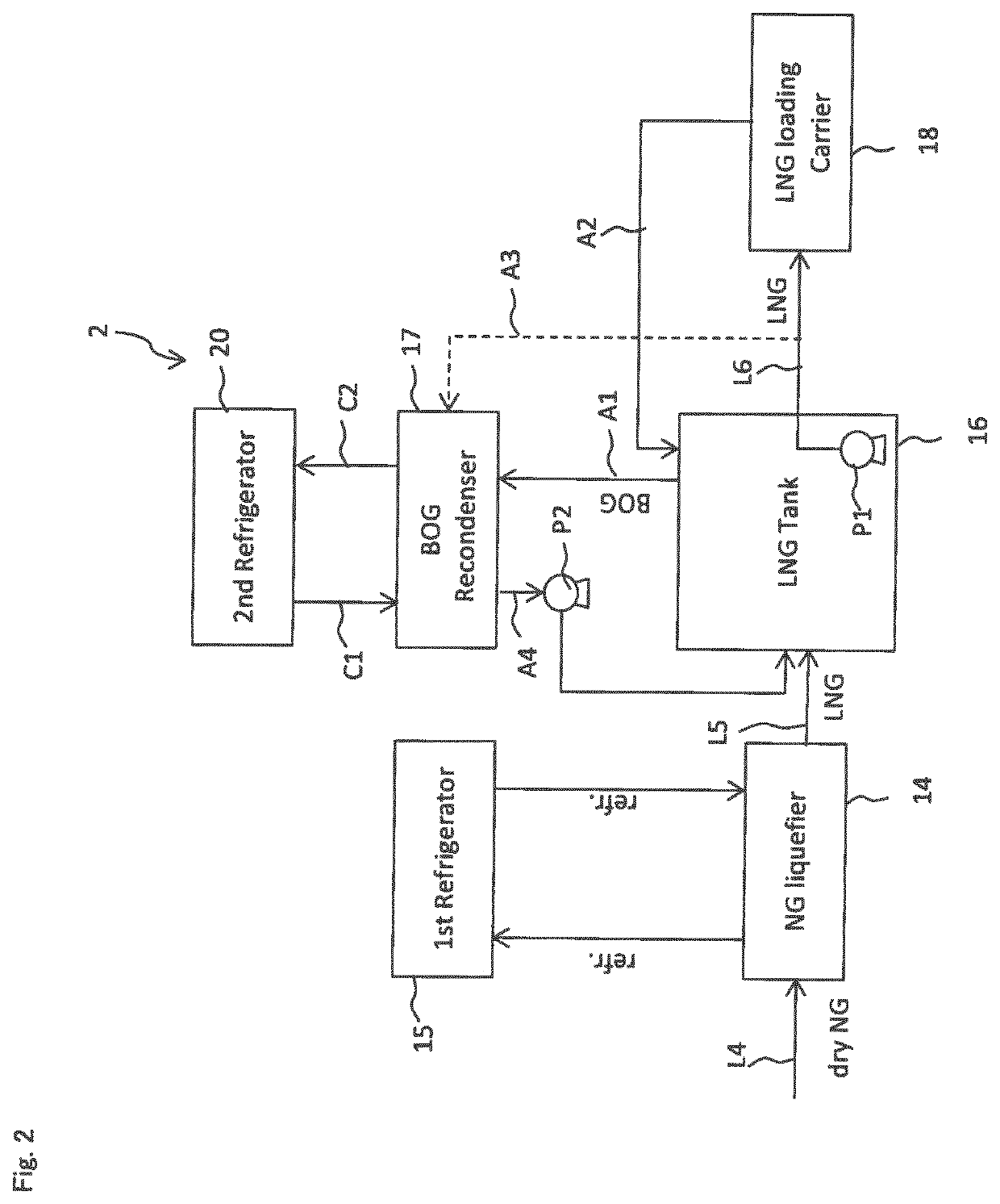
[0111]An LNG production system 2 of embodiment 2 will be described with use of FIG. 2. Components with the same reference signs as those in the LNG production system 1 of embodiment 1 have the same functions, and therefore, explanation of the components will be omitted, or will be made briefly.
[0112]The LNG production system 2 of embodiment 2 has the first refrigerator 15 and a second refrigerator 20. The first refrigerator feeds a refrigerant to a cooling device 14. The second refrigerator 20 feeds the refrigerant (liquid refrigerant) to the recondenser 17 through a refrigerant line C1 (corresponding to B1 in FIG. 1), and returns the refrigerant used as a cold source in the recondenser 17 through a return line C2 (corresponding to B2 in FIG. 1).
[0113]Consequently, since the second refrigerator 20 is provided separately from the first refrigerator 15, it is not necessary to supply the refrigerant to the operating cooling device 14 from the large refrigerator and supply the refrigera...
embodiment 3
[0114]An LNG production system 3 of embodiment 3 will be described with reference to FIG. 3. Components with the same reference signs as those in the LNG production system 1 of embodiment 1 have the same functions, and therefore, explanation of the components will be omitted, or will be made briefly.
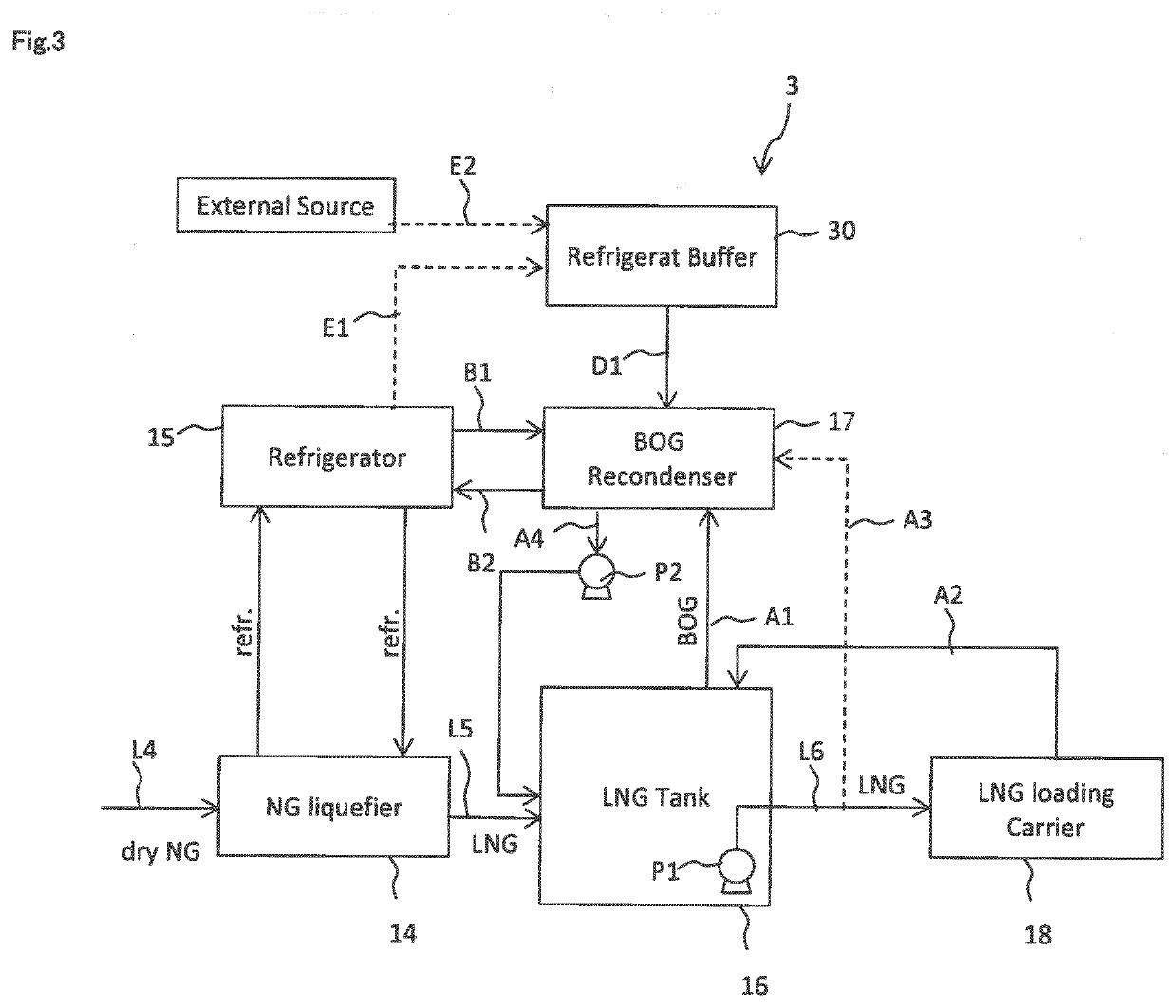
[0115]The recondenser 17 of the LNG production system 3 of embodiment 3 can perform a first recondensation processing of liquefying BOG by the refrigerant fed from the refrigerator 15, and a second recondensation processing that liquefies BOG by the refrigerant fed from the refrigerator 15 and a refrigerant fed from a refrigerant buffer 30 in order to process more BOG than BOG at the time of the first recondensation processing by switching the first and the second recondensation processings to each other.
[0116]In the refrigerant buffer 30, the refrigerant is supplied from the refrigerator 15 through a first supply line E1 and / or the refrigerant is supplied from an external refrigerant so...
PUM
 Abstract
Description
Claims
Application Information