Surgical frame having translating lower beam and moveable linkage or surgical equipment attached thereto and method for use thereof

a surgical frame and lower beam technology, applied in the field of surgical frames, can solve the problems that the surgical equipment attached directly to the surgical frame could interfere with the movement of the main beam or the translating lower beam during surgery, and achieve the effect of improving the accuracy of the surgical process

Active Publication Date: 2020-02-27
WARSAW ORTHOPEDIC INC
View PDF15 Cites 26 Cited by
  • Summary
  • Abstract
  • Description
  • Claims
  • Application Information

AI Technical Summary

Benefits of technology

[0005]The present invention in yet another preferred embodiment contemplates a reconfigurable surgical frame and surgical equipment supportively and moveably attached to the reconfigurable surgical frame including the reconfigurable surgical frame including a support platform, a first support portion, a second support portion, and a main beam spaced from the ground by the support platform, the first support portion, and the second support portion, the support platform including a translating beam moveable relative to portions of the support platform between a first position at or adjacent a first lateral side of the surgical frame and a second position at or adjacent a second lateral side of the surgical frame, and the support platform including a linear movement mechanism including an attachment surface moveable via actuation of the linear movement mechanism between a first position at or adjacent a first end of the translating beam and a second position closer to a second end of the translating b...

Problems solved by technology

Surgical equipment requiring support by moveable carts is oftentimes used during spinal surgery.
However, moveable carts and surgical equipm...

Method used


Image

  • Surgical frame having translating lower beam and moveable linkage or surgical equipment attached thereto and method for use thereof
  • Surgical frame having translating lower beam and moveable linkage or surgical equipment attached thereto and method for use thereof
  • Surgical frame having translating lower beam and moveable linkage or surgical equipment attached thereto and method for use thereof

Examples


Embodiment Construction

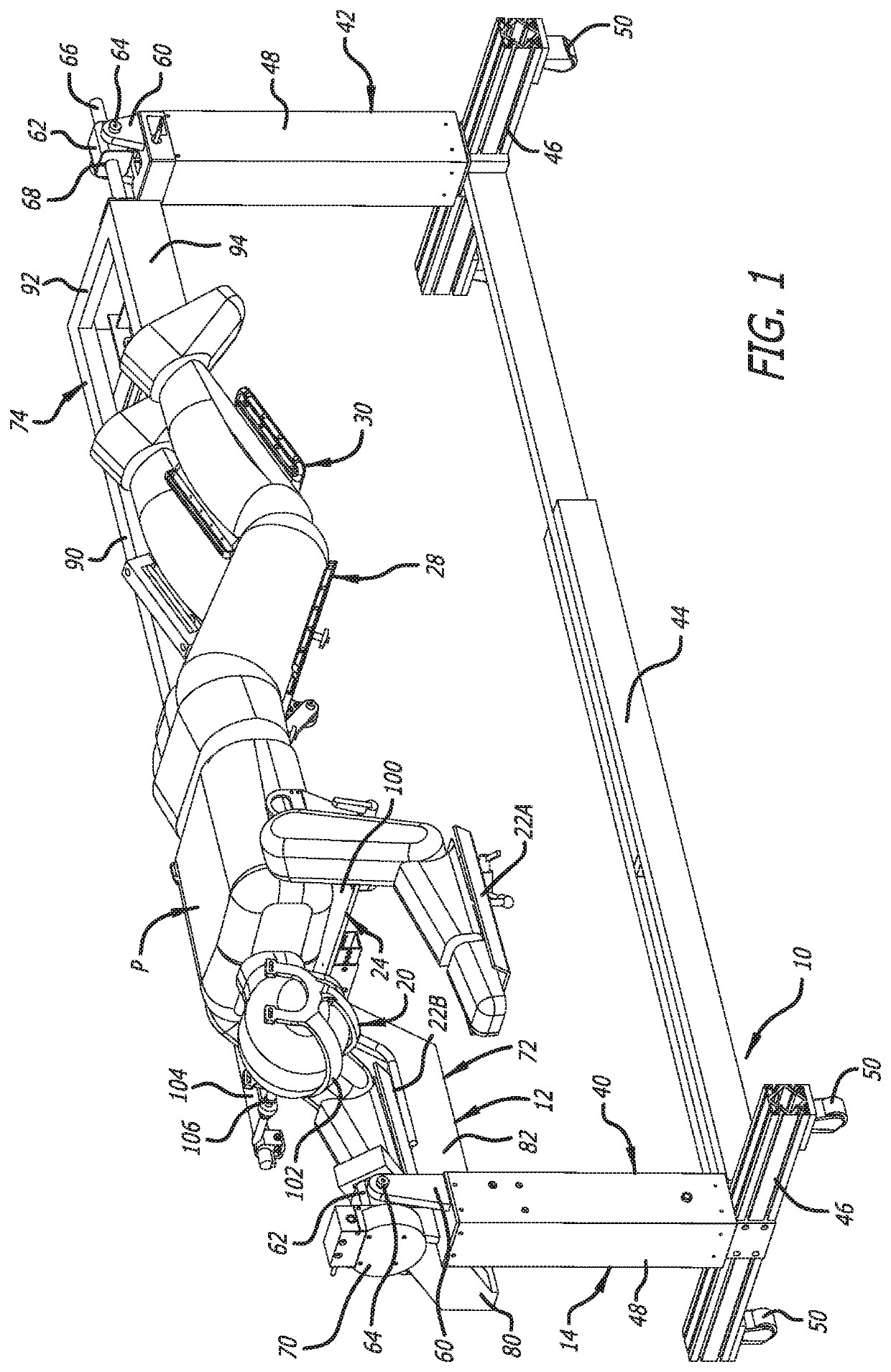
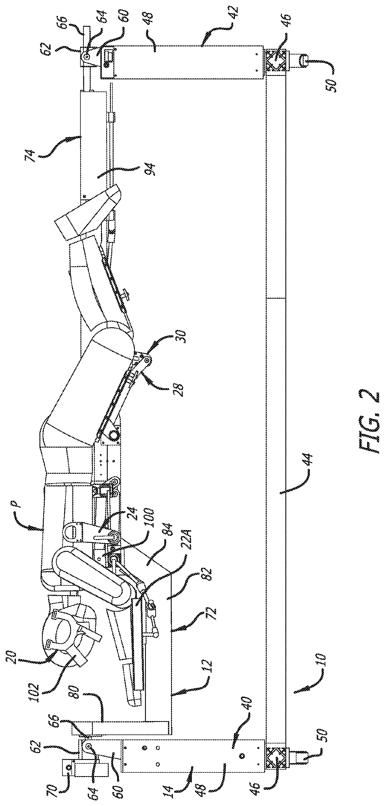
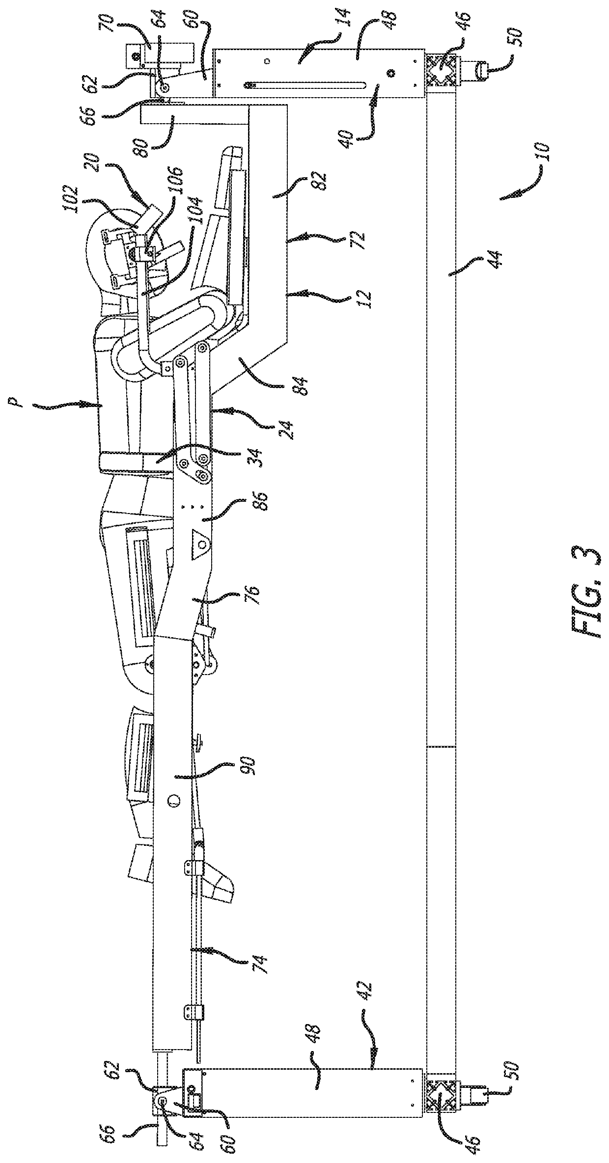
[0052]FIGS. 1-26 depict a prior art embodiment and components of a surgical support frame generally indicated by the numeral 10. FIGS. 1-26 were previously described in U.S. Ser. No. 15 / 239,256, which is hereby incorporated by reference herein in its entirety. Furthermore, FIGS. 27-30 were previously described in U.S. Ser. No. 15 / 639,080, which is hereby incorporated by reference herein in its entirety.

[0053]As discussed below, the surgical frame 10 serves as an exoskeleton to support the body of the patient P as the patient's body is manipulated thereby, and, in doing so, serves to support the patient P such that the patient's spine does not experience unnecessary torsion.

[0054]The surgical frame 10 is configured to provide a relatively minimal amount of structure adjacent the patient's spine to facilitate access thereto and to improve the quality of imaging available before and during surgery. Thus, the surgeon's workspace and imaging access are thereby increased. Furthermore, rad...


PUM


Abstract

A surgical frame and method for use thereof is provided. The surgical frame is capable of reconfiguration before, during, or after surgery using a moveable main beam supporting a patient thereon. The surgical frame includes a translating lower beam that is moveable between at least a first lateral position and a second lateral position, and a linkage and/or surgical equipment supportively and moveably attached to the translating lower beam or interconnected with the translating lower beam via the linkage. The linkage and/or the surgical equipment are moveable between a first position at or adjacent a first end of the translating lower beam and a second position closer to a second end of the translating lower beam than the first position. The translating lower beam is used to join a first support portion and a second support portion of the surgical frame to one another, and movement of the translating lower beam affords access to a patient receiving area. A linear movement mechanism can be used to facilitate movement of the linkage and/or the surgical equipment along the translating lower beam to avoid interference with the main beam or the translating lower beam.

Description

BACKGROUND OF THE INVENTIONField of the Invention[0001]The present invention relates to a surgical frame and a method for use thereof incorporating a translating lower beam and a linkage and / or surgical equipment supportively and moveably attached thereto. More particularly, the present invention relates to a surgical frame and a method for use thereof, where the surgical frame includes a translating lower beam that is moveable with respect to the remainder of the surgical frame, and a linkage and / or surgical equipment that are moveable relative to the translating lower beam. More specifically, the present invention relates to a surgical frame and a method for use thereof, where the surgical frame includes a translating lower beam that can be positioned and repositioned relative to the surgical frame, and the surgical frame further includes a linear movement mechanism for positioning and repositioning a linkage and / or surgical equipment supportively and moveably attached to the tran...

Claims


Application Information

Patent Timeline
IPC IPC(8): A61G13/08A61G13/04A61B34/30
CPCA61G13/04A61B2034/304A61G13/123A61G13/08A61G13/122A61G13/121A61G13/0054A61G13/104A61B34/30A61G13/02A61G13/1235A61G13/1245A61G2200/322A61G2200/325A61G2203/30A61G2210/50
Inventor LIM, ROY K.HYNES, RICHARD A.WAUGH, LINDSEY G.MORRISON, MATTHEW M.
Owner WARSAW ORTHOPEDIC INC
Why Eureka
Try Eureka