
Radiation image processing apparatus and radiation image processing method

a radiation image processing and image processing technology, applied in the field of radiation image processing apparatus and radiation image processing method, can solve the problem that the position of the tube at the time of imaging cannot be accurately estimated, and achieve the effect of accurately estimating the position of the tub

Active Publication Date: 2020-02-27
SHIMADZU CORP
View PDF0 Cites 0 Cited by
  • Summary
  • Abstract
  • Description
  • Claims
  • Application Information

AI Technical Summary

Benefits of technology

The present invention provides a radiation image processing apparatus and method that can accurately estimate the position of a tube at the time of imaging. By using a plurality of markers in the captured image and estimating their positions based on the positions of the markers selected as a pair, the apparatus and method can appropriately select a pair even in a case where the phantom is inclined. This results in a correctly estimated position of the tube at the time of imaging. Additionally, the apparatus and method use a central point of a region surrounded by markers in the captured image and a metal marker in the outermost portion in a perpendicular direction as a center of gravity to further enhance the accuracy of the position estimation.

Problems solved by technology

As a result, there is a problem that the position of the tube at the time of imaging cannot be accurately estimated.

Method used


Image

  • Radiation image processing apparatus and radiation image processing method
  • Radiation image processing apparatus and radiation image processing method
  • Radiation image processing apparatus and radiation image processing method

Examples


modification example

[0075]The embodiment described above is to be considered in all respects as illustrative and not restrictive. The scope of the present invention is indicated not by the above description of the embodiment but by the scope of the claims, and further includes all changes (modification examples) within the meaning and scope equivalent to the scope of the claims.

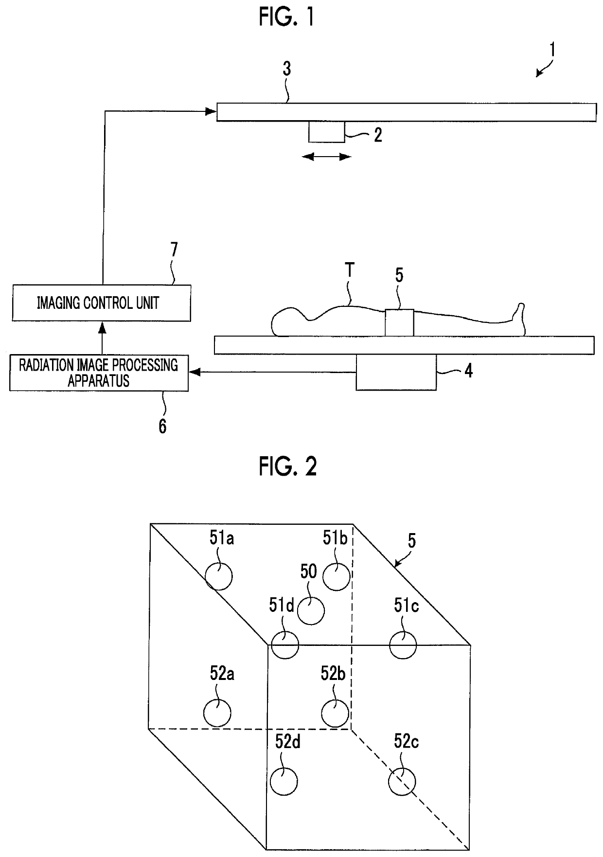
[0076]For example, in the above embodiment, the phantom 5 has the metal marker 50. However, since the metal marker 50 is used to check whether or not the processing in the radiation image processing apparatus 6 is correct or for image reconstruction or the like, the phantom 5 may not have the metal marker 50.


PUM


Abstract

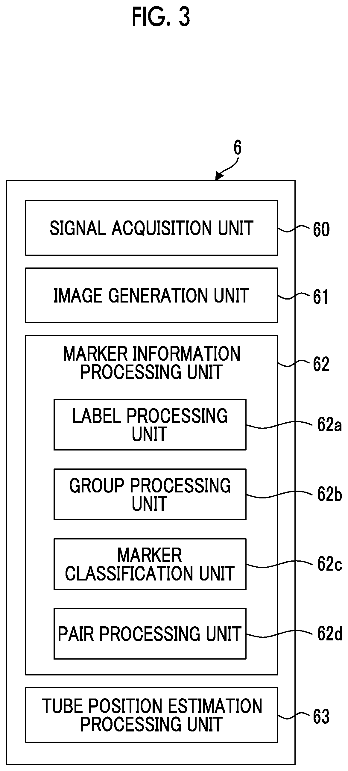
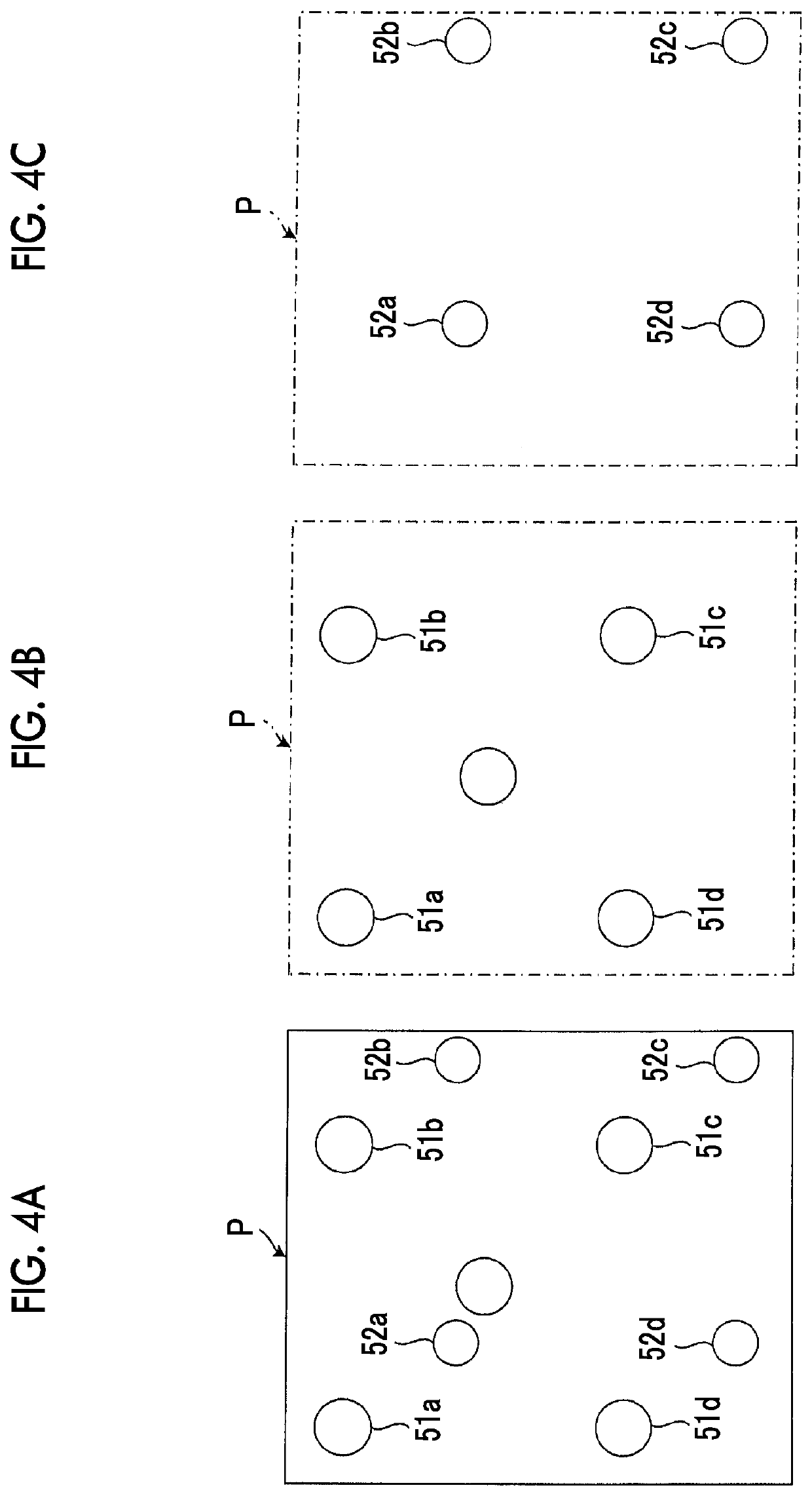
A radiation image processing apparatus includes: a group processing unit classifying a plurality of metal markers into a first group relatively far from a detector and a second group relatively close to the detector based on the area of each image of the plurality of metal markers in a captured image; a marker classification unit classifying the plurality of metal markers based on the relative positions of the plurality of metal markers to on the image plane of the captured image for each of the classified groups; and a pair processing unit selecting the metal markers of the first group and the metal markers of the second group, of which the relative positions match each other, as a pair.

Description

RELATED APPLICATIONS[0001]The contents of Japanese Patent Application No. 2018-145986, on the basis of which priority benefits are claimed in an accompanying application data sheet, is in its entirety incorporated herein by reference.BACKGROUND OF THE INVENTIONField of the Invention[0002]The present invention relates to a radiation image processing apparatus and a radiation image processing method for estimating the position of a tube that is a radiation source.Background Art[0003]A radiation image that performs tomosynthesis acquires signals of a plurality of images by performing imaging while changing the position of a tube that is a radiation source. The radiation image capturing apparatus images a phantom having a pair of metal markers together with a subject, and estimates the position of a tube at the time of imaging based on the position of one pair of metal markers shown in the image (for example, JP-A-2006-181252).SUMMARY OF THE INVENTION[0004]In a configuration in which th...

Claims


Application Information

Patent Timeline
IPC IPC(8): G01T7/00G06T7/73
CPCG01T7/005G06T2207/30204G06T7/74A61B6/44A61B6/52G06T7/73A61B6/584
Inventor MIYAJIMA, TAKAHIROYAMAMOTO, JUNYANISHINO, KAZUYOSHI
Owner SHIMADZU CORP
Learn More