Eureka AIR delivers breakthrough ideas for toughest innovation challenges, trusted by R&D personnel around the world.

Frequency up-conversion device and signal transmission system

a technology of frequency up conversion and signal transmission system, which is applied in the direction of transmission, electrical equipment, etc., can solve the problems of high cost, large amount of data to be transmitted through a limited number of frequency bands, and cost that is greater than the cost of wireless communication, so as to reduce the design cost of the circuit and reduce the cost of the cable for the wired transmission

Active Publication Date: 2020-02-27
WISTRON NEWEB
View PDF0 Cites 1 Cited by
  • Summary
  • Abstract
  • Description
  • Claims
  • Application Information

AI Technical Summary

Benefits of technology

The patent is about a device that can take different signals and efficiently convert them to a specific frequency range. This helps reduce the cost of the device and also reduces the need for expensive cables for transmitting information. The device uses a special circuit that effectively combines signals of different frequencies, allowing for efficient use of space and cost reduction.

Problems solved by technology

Although a plurality of frequency bands are used in radio communication, still a huge amount of the data are required to be transmitted through a limited number of frequency bands.
However, in wired communication, since the data is transmitted by using communication cables over a high frequency band, the cost is greater compared with the wireless communication.
In addition, in a frequency up-conversion process or a frequency down-conversion process of the signals, the signals of different frequencies are processed by their respective mixers, which not only results in high cost, but causes the signals between different frequencies to easily interfere with each other.
Therefore, it has become an important issue to provide a frequency up-conversion device and a signal transmission system that are cost-effective and have fewer mixers.

Method used

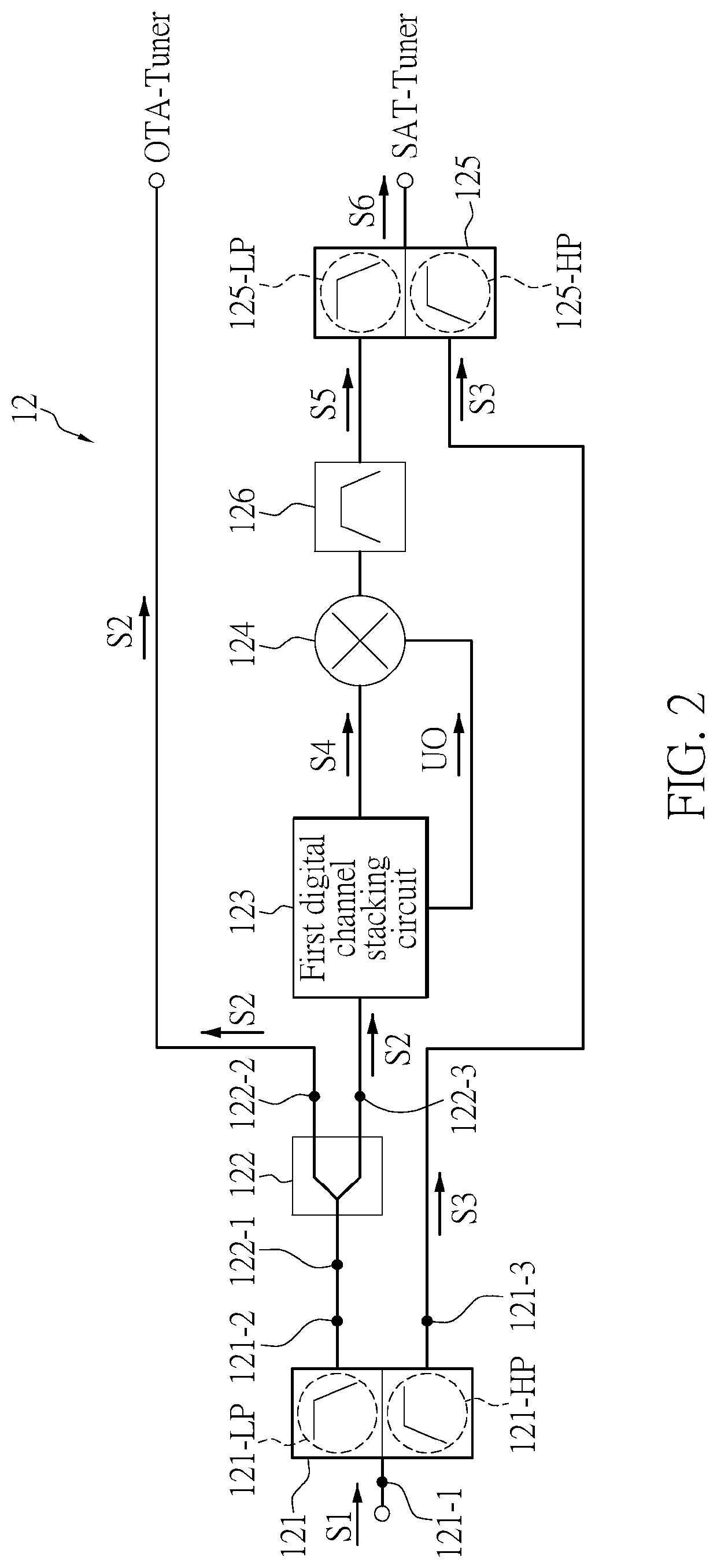
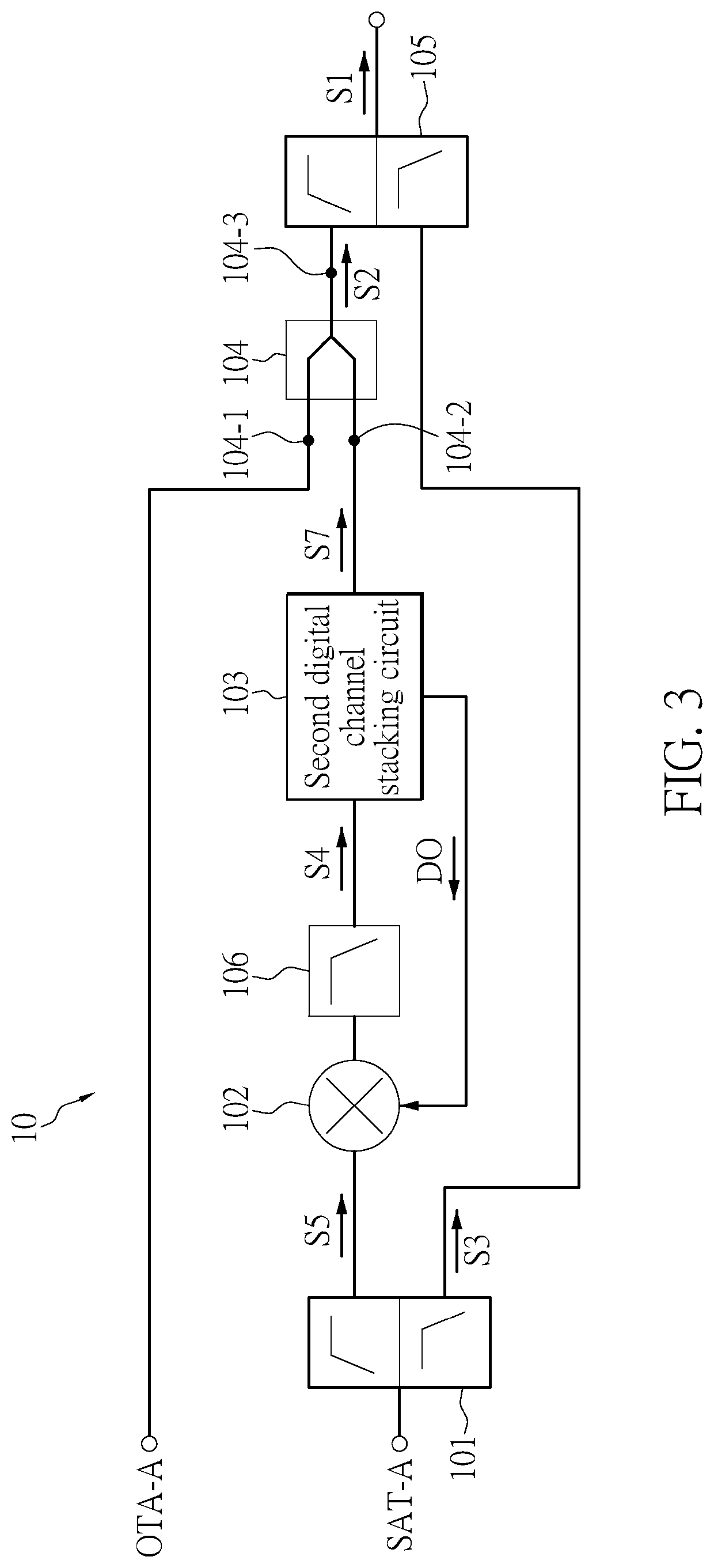

Image

  • Frequency up-conversion device and signal transmission system
  • Frequency up-conversion device and signal transmission system
  • Frequency up-conversion device and signal transmission system

Examples


Embodiment Construction

[0021]The present disclosure is more particularly described in the following examples that are intended as illustrative only since numerous modifications and variations therein will be apparent to those skilled in the art. Like numbers in the drawings indicate like components throughout the views. As used in the description herein and throughout the claims that follow, unless the context clearly dictates otherwise, the meaning of “a”, “an”, and “the” includes plural reference, and the meaning of “in” includes “in” and “on”. Titles or subtitles can be used herein for the convenience of a reader, which shall have no influence on the scope of the present disclosure.

[0022]The terms used herein generally have their ordinary meanings in the art. In the case of conflict, the present document, including any definitions given herein, will prevail. The same thing can be expressed in more than one way. Alternative language and synonyms can be used for any term(s) discussed herein, and no speci...


PUM


Abstract

A frequency up-conversion device and a signal transmission system are provided. A frequency up-conversion device includes a first diplexer, a divider, a digital channel stacking circuit, an up-conversion mixer, and a second diplexer. The first diplexer divides a first signal into a second signal and a third signal. The digital channel stacking circuit transforms the second signal to a fourth signal. The up-conversion mixer mixes the fourth signal and an up-conversion oscillating signal to generate a fifth signal. The second diplexer receives the fifth signal and the third signal to generate a sixth signal for output.

Description

CROSS-REFERENCE TO RELATED PATENT APPLICATION[0001]This application claims the benefit of priority to Taiwan Patent Application No. 107129623, filed on Aug. 24, 2018. The entire content of the above identified application is incorporated herein by reference.[0002]Some references, which may include patents, patent applications and various publications, may be cited and discussed in the description of this disclosure. The citation and / or discussion of such references is provided merely to clarify the description of the present disclosure and is not an admission that any such reference is “prior art” to the disclosure described herein. All references cited and discussed in this specification are incorporated herein by reference in their entireties and to the same extent as if each reference was individually incorporated by reference.FIELD OF THE DISCLOSURE[0003]The present disclosure relates to a frequency up-conversion device and a signal transmission system, and more particularly to ...

Claims


Application Information

Patent Timeline
Patent Type & Authority Applications(United States)
IPC IPC(8): H04B1/00
CPCH04B1/0057H04B1/0096
Inventor CHEN, TZONG-JYHLIAO, WEI-YA
Owner WISTRON NEWEB
Why Eureka
Eureka Blog
Learn More