Automatic stirring cup

a technology of automatic stirring and stirring ball, which is applied in the direction of mixing, rotary stirring mixer, transportation and packaging, etc., can solve the problem that the stirring rod cannot be separately disassembled for cleaning, and achieve the effect of convenient disassembly and cleaning of the stirring ball

Active Publication Date: 2020-03-05
SHENZHEN TOOLFEEL PLASTIC & HARDWARE CO LTD
View PDF0 Cites 1 Cited by
  • Summary
  • Abstract
  • Description
  • Claims
  • Application Information

AI Technical Summary

Benefits of technology

[0018]In the technical solution of the present application, the stirring ball is adsorbed to the bottom of the cavity of the cup body by the magnet, and the bottom of the cup body is provided with the first electrode for electrically connecting the stirring ball and the power base, thereby avoiding the water leakage problem during the use of the automatic stirring cup in the prior art, caused by that the stirring rod needs to extend from the outside of the cup body to the inner cavity of the cup body. At the same time, the stirring ball and the cup body are connected by magnets, so the stirring ball could be conveniently disassembled from the cup body to facilitate the cleaning of the stirring ball.

Problems solved by technology

Since the stirring rod is a movable component, during the use of the stirring rod, it will easily cause the water leakage in a place in the bottom of the stirring cup body connecting the stirring rod, and the stirring rod extends from the bottom of the cup body into the cup body of the stirring cup, so the stirring rod cannot be separately disassembled for cleaning.

Method used


Image

  • Automatic stirring cup
  • Automatic stirring cup

Examples


embodiment 1

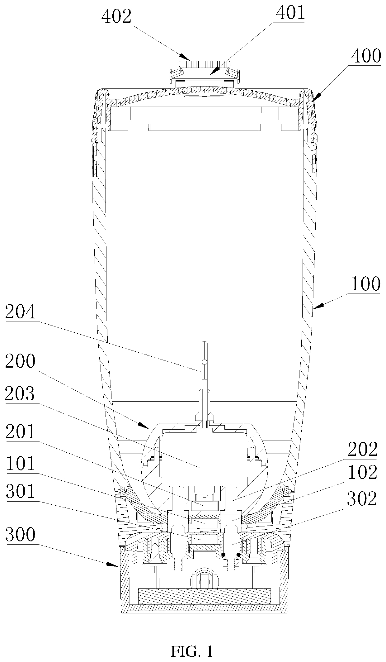
[0030]In an embodiment, the stirring ball 200 comprises a stirring ball shell, a stirring rod 204, and a driving motor 203;

[0031]The stirring rod 204 extends outward from the inside of the stirring ball shell, and the driving motor 203 is arranged inside the stirring ball shell, and the driving motor 203 is used for driving the stirring rod 204 to rotate.

[0032]In the present embodiment, the driving motor 203 is sealed inside the stirring ball shell, and is supplied power through a second electrode 202 on the shell, so the driving motor 203 could drive the stirring rod 204 to rotate, to stir the mixture placed into the cup body of the stirring cup.

embodiment 2

[0033]In an embodiment, a second electrode 202 is arranged at the stirring ball shell, and one end of the second electrode 202 is electrically connected to the driving motor 203, and the other end of the second electrode 202 is matched with the first electrode 102 at the bottom of the cavity of the cup body 100.

[0034]In the present embodiment, when the stirring ball 200 is adsorbed to the cup body 100 of the stirring cup by the magnets, the second electrode 202 on the stirring ball shell contacts the first electrode 102 at the bottom of the cavity of the cup body 100, and by the first electrode 102 of the cup body 100, the stirring ball 200 could be electrically connected with the power base 300 outside the cup body 100.

embodiment 3

[0035]The power base 300 comprises a base shell, a third electrode 302 and a battery arranged inside the base shell; one end of the third electrode 302 is connected to the battery, and the other end of the third electrode is matched with the first electrode 102 at the bottom of the cup body.

[0036]In the present embodiment, the battery is a rechargeable battery, used for supplying power to the driving motor 203 in the stirring ball 200. When the cup body 100 is absorbed to the power base 300 by the magnets, the third electrode 302 at the power base 300 contacts the first electrode 102 at the cup body 100, so the battery supplies power to the driving motor 203 inside the stirring ball 200.


PUM


Abstract

An automatic stirring cup, comprising a cup body, a stirring ball arranged at the bottom of a cavity of the cup body and a power base for supplying power to the stirring ball; a first electrode for electrically connecting the stirring ball and the power base is arranged at the bottom of the cup body; a first magnet is arranged in the stirring ball, and a second magnet matched with the first magnet is arranged at the bottom of the cup body, and the stirring ball and the cup body are magnetically connected; a third magnet matched with the second magnet is arranged at the power base, and the cup body and the power base are magnetically connected. The automatic stirring cup could avoid the water leakage problem during the use of the automatic stirring cup in the prior art.

Description

CROSS REFERENCE TO RELATED APPLICATION[0001]The present application claims the priority of Chinese patent application No. 201811023531.7 filed on Sep. 3, 2018. The contents of the above application are all hereby incorporated by reference.FIELD OF THE INVENTION[0002]The present application relates to a stirring cup, and more particularly, to an automatic stirring cup.BACKGROUND OF THE INVENTION[0003]The driving motor of an existing automatic stirring cup is arranged outside the cup body, and the stirring rod connected to the driving motor passes through the cup body by a central shaft. Since the stirring rod is a movable component, during the use of the stirring rod, it will easily cause the water leakage in a place in the bottom of the stirring cup body connecting the stirring rod, and the stirring rod extends from the bottom of the cup body into the cup body of the stirring cup, so the stirring rod cannot be separately disassembled for cleaning.[0004]Therefore, it is necessary to ...

Claims


Application Information

Patent Timeline
Patent Type & Authority Applications(United States)
IPC IPC(8): B01F7/16B01F13/00B01F15/00
CPCB01F7/162B01F13/002B01F15/00538A47J43/046A47J43/0716A47J43/0465A47J43/0722B01F27/071B01F27/25B01F33/5014B01F27/90B01F27/808B01F33/5011B01F35/3204
Inventor PENG, GUO
Owner SHENZHEN TOOLFEEL PLASTIC & HARDWARE CO LTD
Why Eureka
Try Eureka