Power transmission device, power reception device, and control method for power transmission device

a power transmission device and power reception technology, applied in the direction of charging stations, electric vehicle charging technology, transportation and packaging, etc., can solve the problems of adverse effects of achieve the effect of preventing the size and cost of the power reception device from increasing, reducing the reception power, and lowering the reception power

Active Publication Date: 2020-03-05
TOYOTA JIDOSHA KK
View PDF0 Cites 1 Cited by
  • Summary
  • Abstract
  • Description
  • Claims
  • Application Information

AI Technical Summary

Benefits of technology

[0023]According to the control method mentioned above, the power transmission efficiency is estimated based on the relative position of the power reception device to the power transmission coil the initial factor) before the start of power transmission. If the estimated power transmission efficiency is equal to or higher than the threshold, the power transmission is started at the first power lower than the second power. As a result, it is possible to lower the reception power at the start of power transmission, which makes it possible to design the allowable reception power of the power reception device to a lower value, preventing the size and cost of the power reception device from increasing. On the other hand, if the estimated power transmission efficiency is smaller than the threshold, the power transmission is started at the second power higher than the first power. Thereby, it is possible to prevent the reception power from being reduced too low at the start of the power transmission. As a result, it is possible to transmit an appropriate amount of power in a wireless manner from the power transmission device to the power reception device while preventing the size and cost of the power reception device from increasing.

Problems solved by technology

As a result, the size and cost of the power reception device may increase adversely.

Method used


Image

  • Power transmission device, power reception device, and control method for power transmission device
  • Power transmission device, power reception device, and control method for power transmission device
  • Power transmission device, power reception device, and control method for power transmission device

Examples


first embodiment

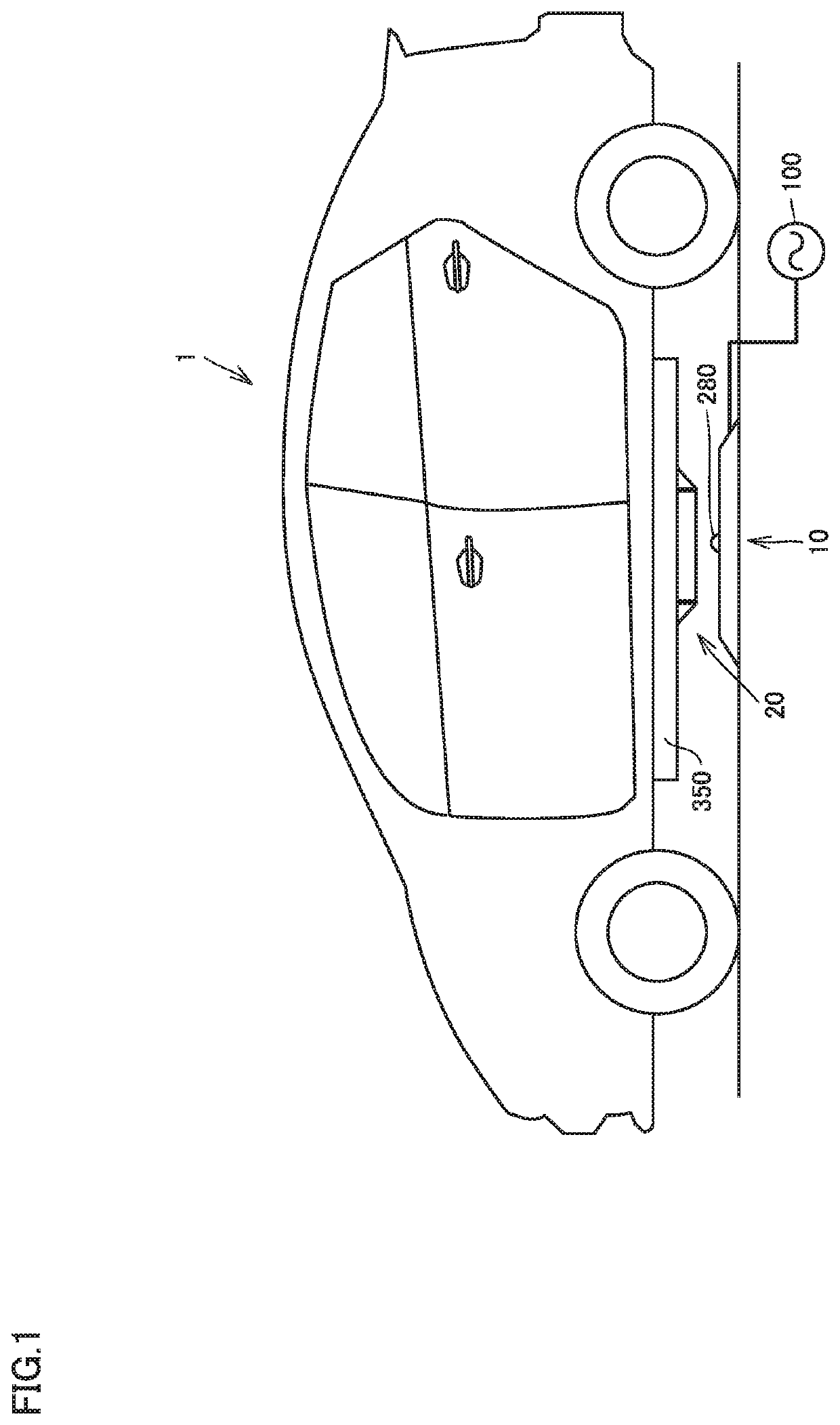
[0038]FIG. 1 is an external view of a power transfer system including a power transmission device 10 according to the present embodiment. The power transfer system includes a vehicle 1 and a power transmission device 10. The vehicle 1 is equipped with a power reception device 20. The power reception device 20 is disposed on the bottom surface of the vehicle 1, the example, on a lower surface (facing the road) of a power storage device 350 installed, on the bottom surface of the vehicle 1, The vehicle 1 is configured to travel by using the power supplied from the power transmission device 10 and stored in the power storage device 350.

[0039]The power transmission device 10 receives power from an AC power supply (for example, a commercial power supply) 100. The power transmission device 10 is installed on the ground. The power transmission device 10 is configured to transmit power in a wireless manner to the power reception device 20 through a magnetic field when the vehicle 1 is align...

second embodiment

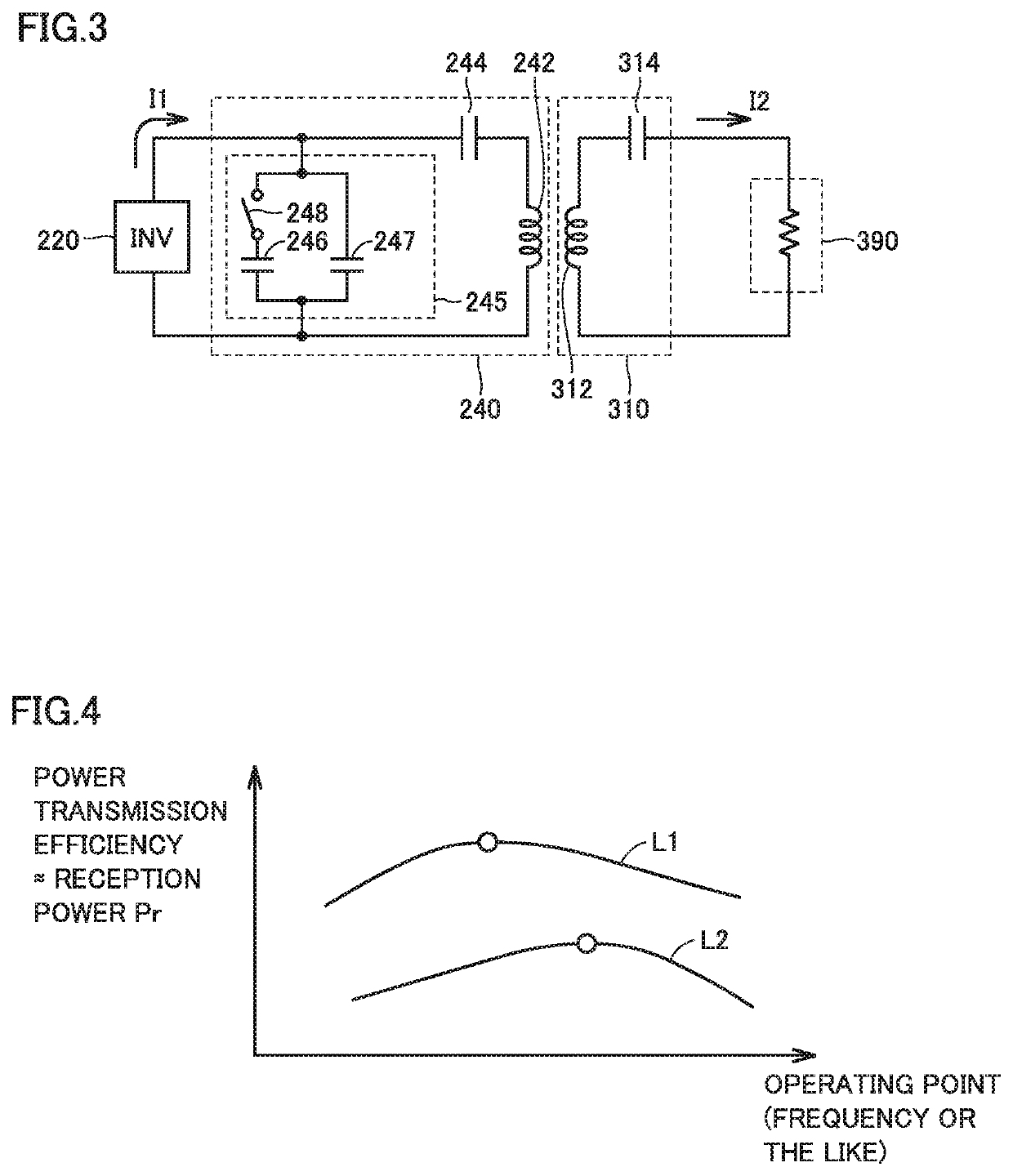
[0109]In the first embodiment described above, based on the fact that the power transmission efficiency for transmitting power in a wireless manner may not be determined unless the operating point search control is performed while the power is being actually transmitted, the operating point search control is performed while the transmission power Ps is being lowered to the first power P1 in advance, which makes it possible to lower the reception power Pr during the operating point search control.

[0110]In the second embodiment, based on the fact that the power transmission efficiency in a wireless manner is greatly affected by the initial factors rather than the variable factors, the power transmission efficiency is estimated based on the relative, position of the power reception device 20 to the power transmission coil 242 of he power transmission device 10 (i.e., the initial factor) before the start of power transmission, and whether the power transmission power Ps is set to the fi...


PUM


Abstract

The power transfer system includes a power transmission device and a power reception device disposed in the vehicle. The power transmission device includes a power transmission coil configured to transmit power in a wireless manner to the power reception device, an inverter configured to generate an AC transmission power and supply it to the power transmission coil, and a power supply ECU. When the transmission of power to the power reception device is started, the power supply ECU sets the transmission power at the start o power transmission to a first power which is lower than a second power, and performs the operating point search control in that state. If the reception power is lower than a tai et reception power after the operating point search control is completed, the power supply ECU sets the transmission power to the second power which is higher than the first power.

Description

CROSS REFERENCE TO RELATED APPLICATIONS[0001]This nonprovisional application claims priority to Japanese Patent Application No. 2018-162612 filed on Aug. 31, 2018 with, the Japan Patent Office, the entire contents of which are hereby incorporated by reference.BACKGROUNDField[0002]The present disclosure relates to a power transmission device that transmits power in a wireless manner, a power reception device, and a control method for the power transmission device.Description of the Background Art[0003]Japanese Patent Laying-Open No. 2018-7509 discloses a system for transmitting power in a wireless manner from a power transmission device disposed outside a vehicle to a power reception device mounted on the vehicle. The power transmission device included in the system includes a power transmission coil, an inverter, and a controller. The power transmission coil is configured to transmit power in a wireless manner to a power reception coil included in the power reception device mounted ...

Claims


Application Information

Patent Timeline
Patent Type & Authority Applications(United States)
IPC IPC(8): B60L53/66B60L53/12H02J50/12H02J7/02H02J50/80
CPCH02J50/12B60L53/12H02J50/80B60L53/66H02J7/025B60L53/122B60L53/126B60L53/39B60L53/37Y02T90/16Y02T10/70Y02T10/7072Y02T90/14Y02T90/12H02J50/90
Inventor NIWA, YAMATO
Owner TOYOTA JIDOSHA KK
Why Eureka
Try Eureka