System for Determining a Relative Position and/or a Relative Distance of a Transmitter with Respect to a Receiver, and Inductive Vehicle Charging System Having Such a System

a technology for determining a relative position and/or a relative distance of a transmitter and a receiver, which is applied in vehicle position/course/altitude control, process and machine control, instruments, etc., can solve the damping change of the positioning signal received in the floor module, and achieve the effect of preventing electrical overload of the receiver and optimizing the signal strength

Pending Publication Date: 2021-08-26
BRUSA ELECTRONICS AG
View PDF0 Cites 2 Cited by
  • Summary
  • Abstract
  • Description
  • Claims
  • Application Information

AI Technical Summary

Benefits of technology

[0025]The proposed system thus makes it possible, in particular, to dynamically adapt the emitted signal strength and / or the carrier frequency of the signals emitted by the transmitter S1 when the transmitter S1 and the receiver E2 approach, so that it is ensured that an optimal signal strength is always received in the receiver E2. This optimal signal strength always allows for an optimal evaluation of the relative position or the relative distance from the transmitter S1 with respect to the receiver E2 and prevents electrical overload of the receiver E2.
[0026]By changing the carrier frequency, the transmitted signal SigS1(t) is detuned, so that a lower reception power is generated in the receiver, which operates on a target carrier frequency. In addition or as an alternative to adapting the signal strength of the signals SigS1(t) emitted by the transmitter S1, the damping in the signal chain in the receiver E2 is advantageously adapted for the received signal. This in particular prevents overloading of the receiver E2 and thus increases the service life of the receiver E2.

Problems solved by technology

This change naturally causes a change in the damping of the positioning signal received in the floor module.

Method used


Image

  • System for Determining a Relative Position and/or a Relative Distance of a Transmitter with Respect to a Receiver, and Inductive Vehicle Charging System Having Such a System
  • System for Determining a Relative Position and/or a Relative Distance of a Transmitter with Respect to a Receiver, and Inductive Vehicle Charging System Having Such a System

Examples


Embodiment Construction

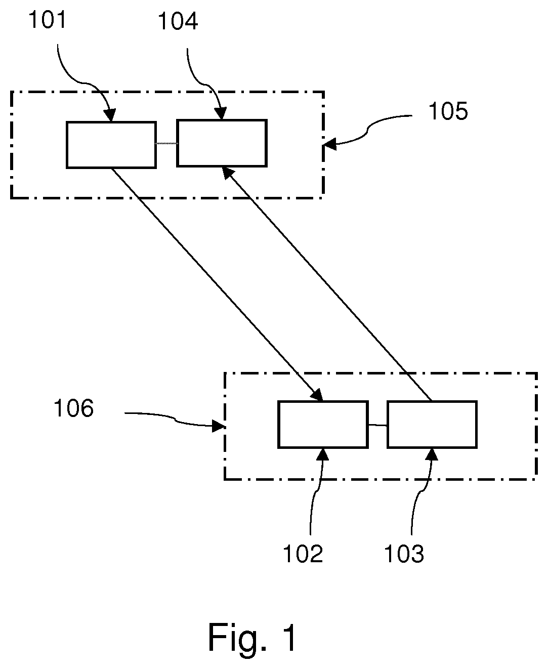
ly schematic structure of a proposed system for determining a relative position POSS1-E2 and / or a relative distance DS1-E2 of a transmitter S1 101 with respect to a receiver E2 102. The system includes the transmitter S1 101 for wirelessly emitting signals SigS1(ti) at the time ti, with time transit index i=1, 2, . . . , the transmitter S1 101 being designed and configured to adjust a signal level P(SigS1(ti)) and a carrier frequency F(SigS1(ti)) of the signal SigS1(ti).

[0056]The system further includes the receiver E2 102 for receiving the signal SigS1(ti) at the time ti+Δt as signal SigE2(ti+Δt), where Δt is a signal transit time, where: 2Δti+1−ti|. The receiver E2 102 is designed and configured to determine the following:

[0057]a signal level P(SigE2(ti+Δt)) of the received signal SigE2(ti+Δt) and a signal-to-noise ratio SNR(SigE2(ti+Δt)) of the received signal SigE2(ti+Δt),

[0058]a direction of incidence {right arrow over (E)}2 of the received signal SigE2(ti+Δt), and,

[0059]on the...


PUM


Abstract

A system for determining a relative position and/or a relative distance of a transmitter with respect to a receiver, including: the transmitter for wirelessly emitting signals at the time ti, the receiver or receiving a signal at the time ti+Δt, wherein the receiver is configured to determine the following: a signal level P and/or a signal-to-noise ratio SNR of the received signal, a direction of incidence of the received signal and, on the basis of P and E, a relative position POS of the transmitter with respect to the receiver and/or a relative distance D between the transmitter and the receiver, and another transmitter connected to the receiver and intended to wirelessly transmit P, SNR, POS, and/or D to another receiver connected to the transmitter.

Description

CROSS-REFERENCE TO RELATED APPLICATIONS[0001]The present application is the U.S. National Phase of PCT / EP2019 / 066659, filed on Jun. 24, 2019, which claims priority to German Patent Application No. 10 2018 115 795.9, filed on Jun. 29, 2018, the entire contents of which are incorporated herein by reference.BACKGROUNDField[0002]The invention relates to a system for determining a relative position and / or a relative distance of a transmitter with respect to a receiver, and to an inductive vehicle charging system having such a system.Related Art[0003]Inductive vehicle charging systems typically include a floor module and a vehicle module, electrical energy being transmitted inductively from the floor module to the vehicle module. For an optimal energy transfer it is necessary that the vehicle module is optimally positioned relative to the floor module. Since the floor module is typically installed in a stationary manner, the vehicle must be guided in such a way that it reaches this optima...

Claims


Application Information

Patent Timeline
Patent Type & Authority Applications(United States)
IPC IPC(8): B60L53/126B60L53/36B60L53/38G01S5/02H02J50/10H02J50/90H02J7/00
CPCB60L53/126B60L53/36B60L53/38G05D1/0225H02J50/10H02J50/90H02J7/00032G01S5/0284G01S5/0009G05D2201/0213B60L53/122H02J7/00034H02J2310/48Y02T10/7072Y02T10/70Y02T90/14Y02T90/12B60K6/28B60Y2200/91B60Y2200/92B60Y2300/91
Inventor BÖHLER, LUKASKNUCHEL, RICHARDHANSELMANN, MARC
Owner BRUSA ELECTRONICS AG
Why Eureka
Try Eureka