Charging apparatus
- Summary
- Abstract
- Description
- Claims
- Application Information
AI Technical Summary
Benefits of technology
Problems solved by technology
Method used
Image
Examples
first embodiment
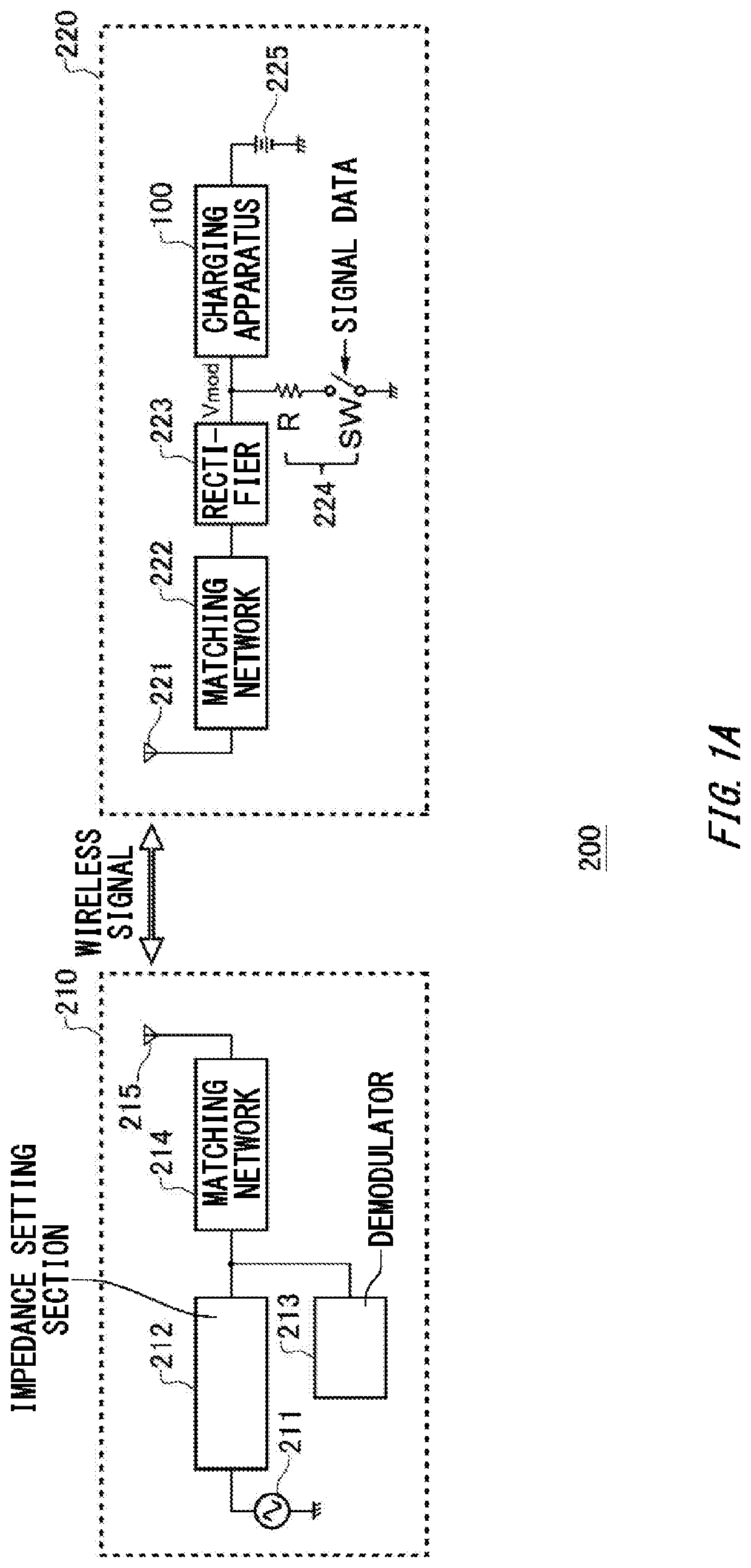
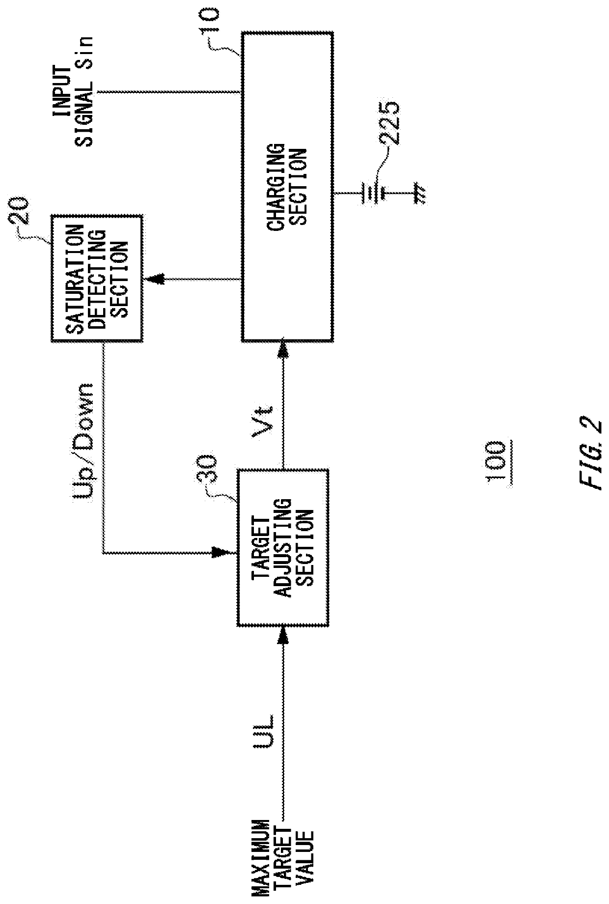
[0033]FIG. 3A shows an example of a detailed configuration of the charging apparatus 100 according to a The charging section 10 includes a switching section 11, a diode section 12, a coil section 13, the output detecting section 14, a difference detecting section 15, an integrating section 16, and a pulse generating section 17. The feedback loop of the charging section 10 is formed by the switching section 11, the coil section 13, the output detecting section 14, the difference detecting section 15, the integrating section 16, and the pulse generating section 17.
[0034]The switching section 11 switches whether an input terminal and the output detecting section 14 are connected. In this way, the switching section 11 switches whether the battery 225 is being charged with the power corresponding to the input signal Sin. The switching section 11 includes a switch SW1 formed by a MOS switch or the like. One end of the switch SW1 is connected to the input terminal, and the other end is co...
second embodiment
[0055]FIG. 4B shows an example of a timing chart of the charging apparatus 100 according to the The timing chart of the present example shows whether load modulation of the power supply system 200 is possible. If the feedback loop is normal, load modulation is possible. On the other hand, when the feedback loop is saturated and the impedance drops, load modulation becomes not effective. Furthermore, the interval control section 31 of the present embodiment changes the interval signal to a predetermined value. The timing of the output of the Up / Down counter changes according to the interval signal.
[0056]As an example, the charging apparatus 100 can decrease the time ratio during which the feedback loop is saturated, by making the time interval variable. Specifically, the charging apparatus 100 can decrease the time ratio during which the feedback loop is saturated by shortening the time interval after the saturation detecting section 20 has detected saturation. In this way, the char...
third embodiment
[0068]FIG. 5B shows an example of a timing chart of the charging apparatus 100 according to the The present example shows a case where the time period during which the feedback loop is normal, by setting Duty Limit as the maximum duty setting value.
[0069]In a case where Duty Limit is present, the drop in the input voltage and charging current is less than in a case where Duty Limit is not present. In other words, by setting Duty Limit, the charging apparatus 100 can restrict the amplitude of the input voltage and the charging current, and increase the average charging current.
[0070]The charging apparatus 100 of the present example decreases the time ratio during which the feedback loop is saturated by shortening the time interval after the saturation detecting section 20 has detected saturation, in the same manner as the charging apparatus 100 according to the second embodiment. Therefore, the charging apparatus 100 can reduce the time ratio during which load modulation cannot be p...
PUM
 Abstract
Description
Claims
Application Information
 - R&D Engineer
- R&D Manager
- IP Professional
- Industry Leading Data Capabilities
- Powerful AI technology
- Patent DNA Extraction
Browse by: Latest US Patents, China's latest patents, Technical Efficacy Thesaurus, Application Domain, Technology Topic, Popular Technical Reports.
© 2024 PatSnap. All rights reserved.Legal|Privacy policy|Modern Slavery Act Transparency Statement|Sitemap|About US| Contact US: help@patsnap.com


