Optical wireless power transfer system performing bidirectional communication

a power transfer system and wireless technology, applied in the field of optical wireless power transfer systems, can solve the problems of increasing the volume and weight of the wireless terminal, and achieve the effects of reducing the volume and weight of the terminal, preventing electromagnetic interference, and increasing the distance to perform communication

Active Publication Date: 2020-03-05
LG ELECTRONICS INC
View PDF0 Cites 7 Cited by
  • Summary
  • Abstract
  • Description
  • Claims
  • Application Information

AI Technical Summary

Benefits of technology

[0012]According to the present disclosure, the wireless bidirectional communication is performed using the light, thereby increasing a possible distance to perform communication between terminals.
[0013]Further, according to the present disclosure, an additional battery may not be mounted on the wireless terminal using the light as the power source, thereby reducing the volume and the weight of the terminal.
[0014]Further, according to the present disclosure, the modulated signal may be transmitted and received through the light, thereby preventing electromagnetic interference (EMI) that occurs based on periphery electronic devices.

Problems solved by technology

However, the wireless terminal provided as described above may require an additional battery to perform wireless communication with the main body, and a volume and a weight of the wireless terminal may be increased because the battery is mounted on the wireless terminal.
Further, as the battery is discharged over time, users may not only periodically replace the battery of the wireless terminal, but also a required function may not be performed through the wireless terminal when the battery is discharged in unexpected situations.

Method used


Image

  • Optical wireless power transfer system performing bidirectional communication
  • Optical wireless power transfer system performing bidirectional communication
  • Optical wireless power transfer system performing bidirectional communication

Examples


Embodiment Construction

[0023]The above-mentioned objects, features, and advantages of the present disclosure will be described in detail with reference to the accompanying drawings. Accordingly, the skilled person in the art to which the present disclosure pertains may easily implement the technical idea of the present disclosure. Preferred embodiments of the present disclosure are described in detail with reference to the accompanying drawings. In the drawings, same reference numerals are used to refer to same or similar components.

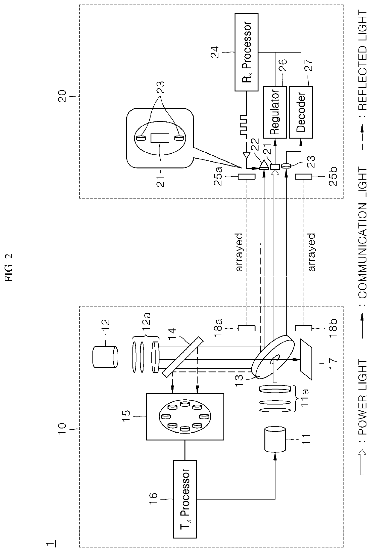
[0024]The present disclosure relates to an optical wireless power transfer system capable of performing bidirectional communication wirelessly using light. Hereinafter, the optical wireless power transfer system of the present disclosure will be described in detail with reference to FIGS. 1 to 6.

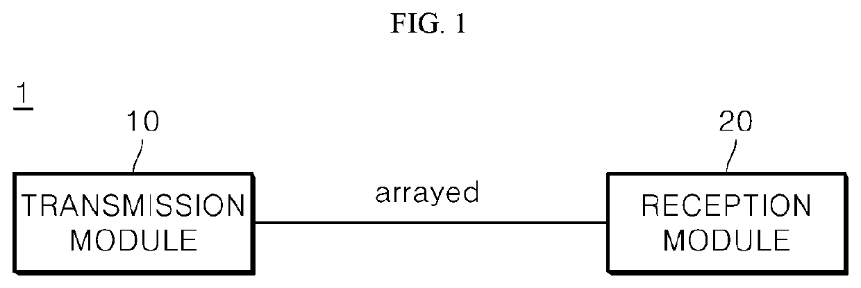
[0025]Referring to FIG. 1, according to the present disclosure, an optical wireless power transfer system 1 may include a transmission module 10 and a reception module 20. The optical ...


PUM


Abstract

An optical wireless power transfer system including a transmission module having a power light source configured to output power light; a communication light source configured to output communication light; a mirror disposed in a light path of the power light source and the communication light source and configured to pass the power light and reflect the communication light; and a transmitting processor configured to modulate the communication light to have a first modulation. The wireless power transfer system also includes a reception module having a photoelectric cell configured to receive the power light from the transmission module and generate power; a retro-reflector configured to retro-reflect the communication light back to the transmission module; and a receiving processor configured to control the retro-reflector to reflect the communication light to have a second modulation based on the power generated by the photoelectric cell.

Description

CROSS-REFERENCE TO RELATED APPLICATION[0001]Pursuant to 35 U.S.C. § 119(a), this application claims the benefit of an earlier filing date and priority to Korean Application No. 10-2018-0103040 filed in the Republic of Korea on Aug. 30, 2018, the contents of which are incorporated by reference herein in its entirety.BACKGROUND OF THE INVENTION1. Field of the Invention[0002]An optical wireless power transfer system performing wireless bidirectional communication using light is disclosed herein.2. Discussion of the Related Art[0003]Recently, in a home appliance market, a main body that performs a main function and a wireless terminal capable of performing an additional function in conjunction with the main body may be provided together. For example, in the cooktop market, which has recently greatly increased in size, the cooktop may include a main body that performs a function for heating food, and a detachable knob switch that may be removably attached to the main body and may perform...

Claims


Application Information

Patent Timeline
Patent Type & Authority Applications(United States)
IPC IPC(8): H04B10/114H04B10/80H04B10/54H04B10/69H02J50/30H02J50/80
CPCH04B10/54H04B10/1143H04B10/808H02J50/80H02J50/30H04B10/69H04B10/807H04B10/1125
Inventor KIM, KYUNGHWANYUK, GYUNGHWANJUNG, BYUNGSANG
Owner LG ELECTRONICS INC
Why Eureka
Try Eureka