Method for controlling a wind turbine

Active Publication Date: 2020-03-12
WOBBEN PROPERTIES GMBH
View PDF7 Cites 2 Cited by
  • Summary
  • Abstract
  • Description
  • Claims
  • Application Information

AI Technical Summary

Benefits of technology

[0009]Provided is a method that provides improved control of a generator of electrical energy in a vulnerable grid state, in particular in order to counteract a potential grid failure. A method for controlling a generator of electrical energy connected to a grid connection point of an electrical supply grid is proposed. Accordingly, electrical power is regularly fed into the electrical supply grid at a first working point. Such a working point may be determined for example by the active power fed in and possibly the reactive power fed in. Regular feeding is such feeding that is not changed or affected by a disruption in the electrical supply grid or a disruption of the feed into the electrical supply grid. Regular feeding is consequently feeding without any disruption.

Problems solved by technology

While the generator is being operated regularly at this first working point, a first interruption or change of the feed, in particular of the active power, so that no power or a changed power is fed into the electrical supply grid, occurs when there is, or it is indicated that there is, a disruption in the electrical supply grid or a disruption of the feed into the electrical supply grid.

Method used


Image

  • Method for controlling a wind turbine
  • Method for controlling a wind turbine
  • Method for controlling a wind turbine

Examples


Embodiment Construction

[0064]In the following text, identical designations may be provided for elements that are similar but not identical, or they may also be provided for elements that are only represented schematically or symbolically and may differ in details, which however are not relevant for the respective explanation.

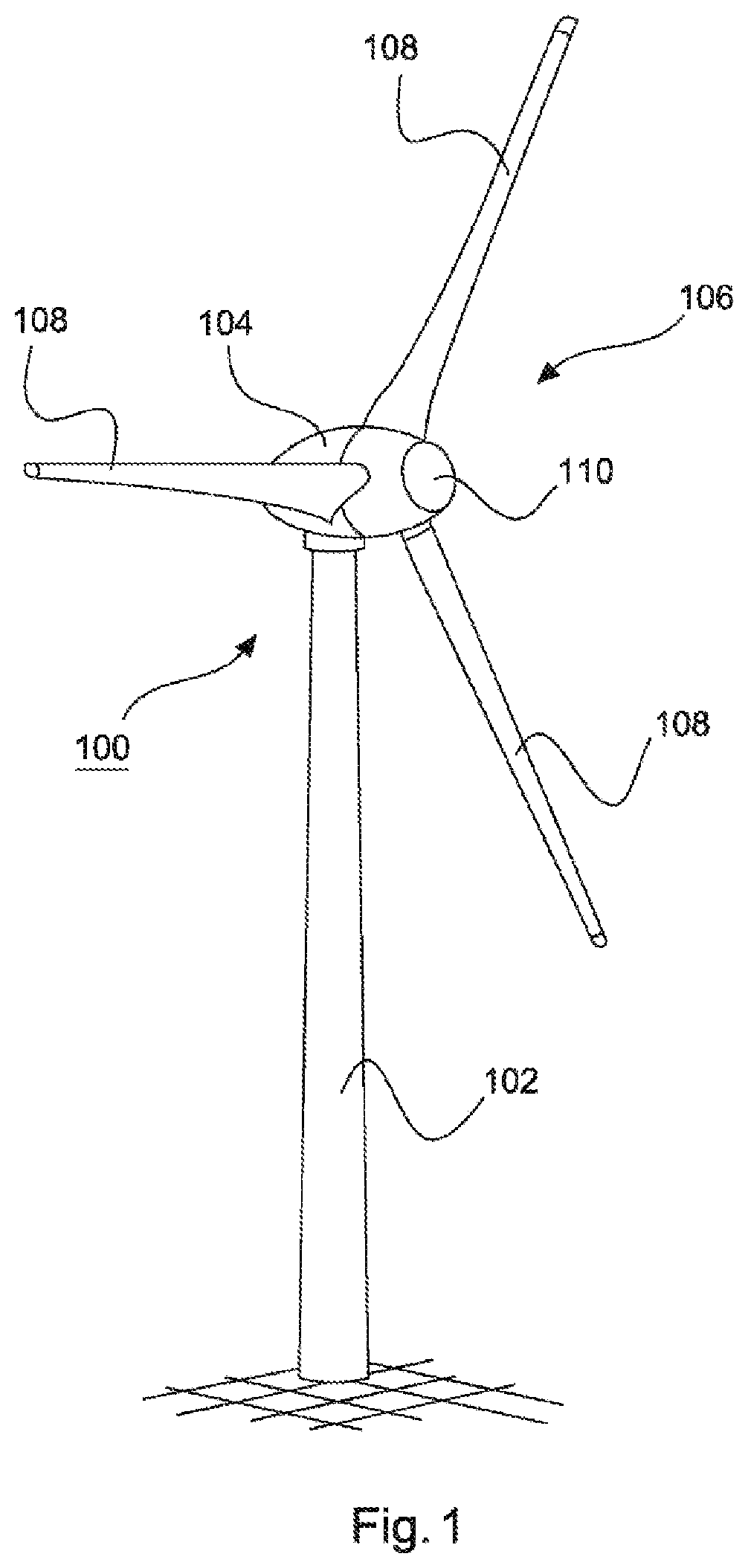
[0065]FIG. 1 shows a wind power installation 100 for generating electrical energy, with a tower 102 and a nacelle 104. Arranged on the nacelle 104 is a rotor 106 with three rotor blades 108 and a spinner 110. During operation, the rotor 106 is set in a rotational motion by the wind and thereby drives a generator in the nacelle 104.

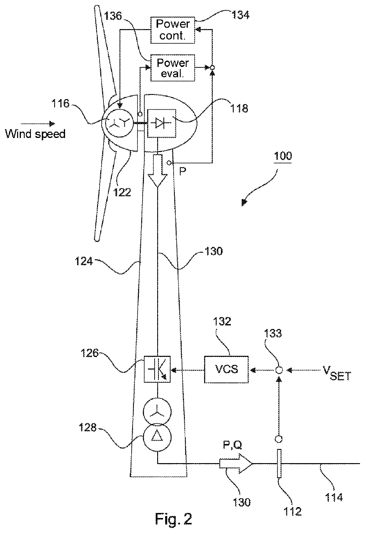
[0066]FIG. 2 schematically shows a wind power installation 100, which is connected by way of a grid connection point 112 to an electrical supply grid 114. For simplicity, the electrical supply grid 114 is also referred to hereinafter as the grid 114, while these terms can be regarded as synonymous.

[0067]The wind power installation 100 has a generator 116, wh...


PUM


Abstract

A method for controlling a generator of electrical energy connected to a grid connection point of an electrical supply grid, comprising the steps of: regularly feeding electrical reactive power and electrical active power into the electrical supply grid, the generator being operated at a first working point, at which the electrical generator generates electrical reactive power and electrical active power, first interrupting or changing the feeding of the electrical reactive power and/or the electrical active power into the electrical supply grid when there is, or it is indicated that there is, a disruption in the electrical supply grid or a disruption of the feed into the electrical supply grid, resuming the regular feeding of the electrical reactive power and/or electrical active power into the electrical supply grid, the generator performing the resumption at a second working point or being ramped up to the second working point, at which the electrical generator generates and feeds in electrical reactive power and/or electrical active power, and suppressing the resumption of the feeding of the electrical reactive power and/or the electrical active power into the electrical supply grid in such a way that the electrical generator ceases feeding the electrical reactive power and/or the electrical active power for a shut-off period if an interruption has recurred within a predetermined counting time interval, or suppressing the feeding of the electrical reactive power and/or the electrical active power into the electrical supply grid in such a way that the electrical generator ceases feeding the electrical reactive power and/or the electrical active power for a shut-off period if a change of the feed has recurred within a predetermined counting time interval.

Description

BACKGROUNDTechnical Field[0001]The present invention relates to a method for controlling a generator of electrical energy connected to a grid connection point of an electrical supply grid. The present invention also relates to a generator of electrical energy connected to an electrical supply grid, in particular a wind power installation.Description of the Related Art[0002]The feeding of electrical energy into an electrical supply grid, such as for example the European synchronous grid, is generally known. Quite generally, these electrical supply grids usually have a safe grid state—they are therefore stable, in particular with regard to their grid frequency and their grid voltage.[0003]Various grid faults, such as for example a short-circuit, can cause the electrical supply grids to go into a vulnerable grid state, in which for example it is no longer possible for all of the consumers of the supply grid to be supplied with electrical energy. The grid then has a disruption.[0004]An ...

Claims


Application Information

Patent Timeline
Patent Type & Authority Applications(United States)
IPC IPC(8): H02P9/10H02P9/00F03D9/25
CPCH02P2101/15F03D9/257H02P9/105H02P9/006H02J2300/28H02J3/381H02J3/48H02J3/50F03D7/0284Y02E10/76Y04S10/123H02J3/24Y02E10/72F03D7/04
Inventor KRUSE, MARCEL
Owner WOBBEN PROPERTIES GMBH
Why Eureka
Try Eureka