Carrier structure of woodworking machine spindle

Inactive Publication Date: 2020-03-19
HSU CHUN JEN
View PDF0 Cites 0 Cited by
  • Summary
  • Abstract
  • Description
  • Claims
  • Application Information

AI Technical Summary

Benefits of technology

[0004]The primary object of the present invention is to provide a carrier structure of a woodworking machine spindle, which can quickly calculate the position

Problems solved by technology

The machining process is cumbersome, the failure rate is h

Method used


Image

  • Carrier structure of woodworking machine spindle
  • Carrier structure of woodworking machine spindle
  • Carrier structure of woodworking machine spindle

Examples


Embodiment Construction

[0015]Embodiments of the present invention will now be described, by way of example only, with reference to the accompanying drawings.

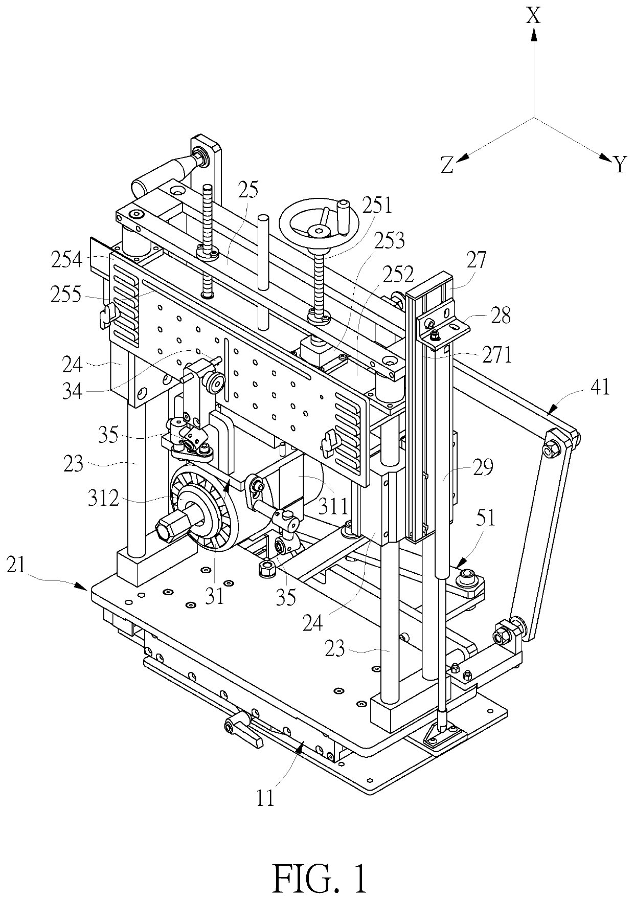
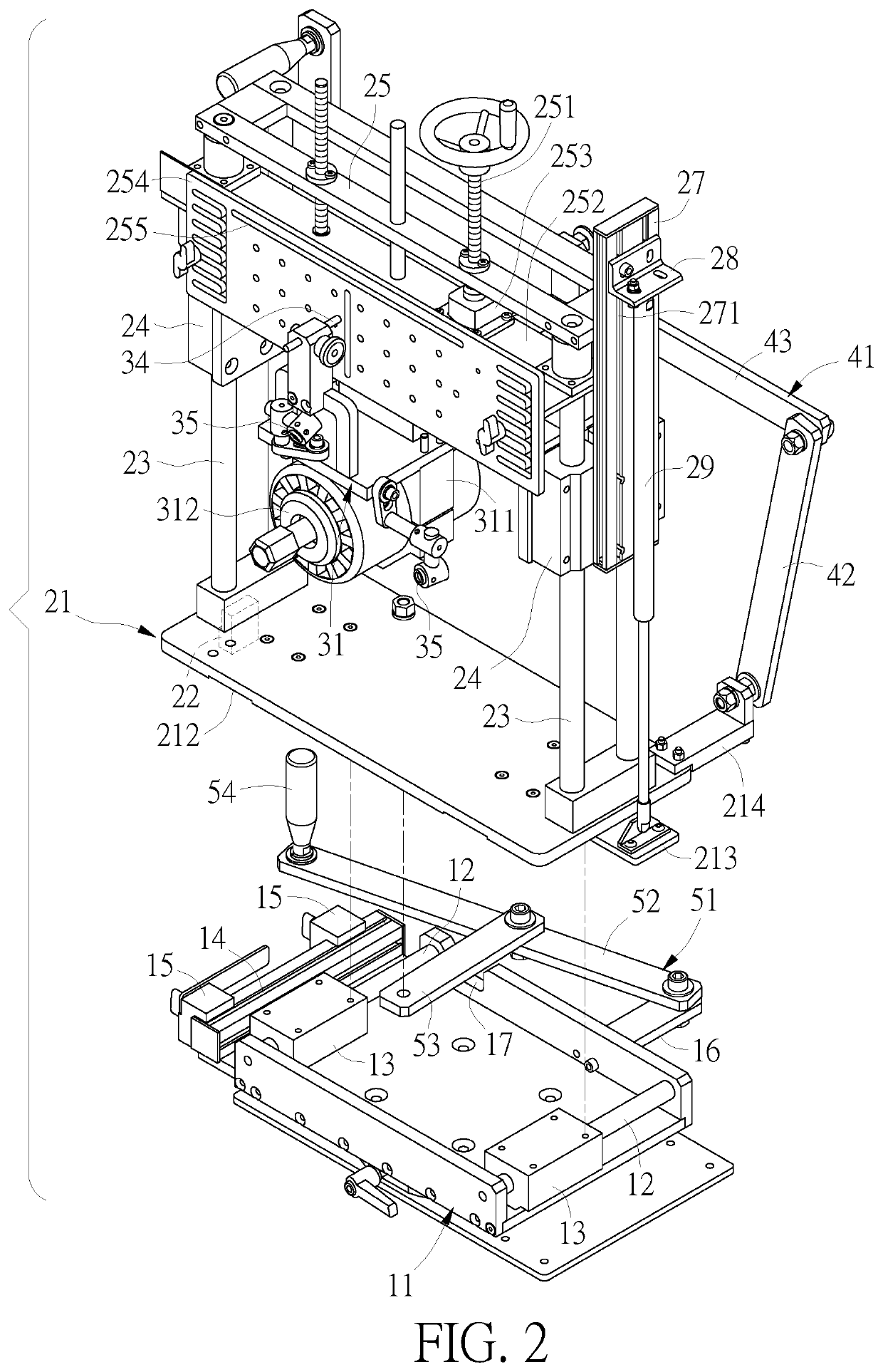
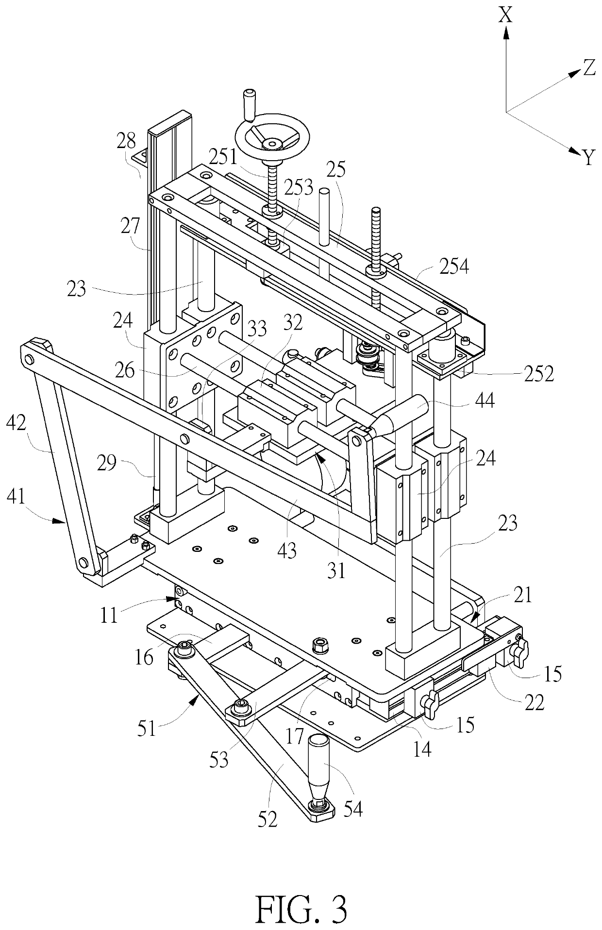
[0016]Referring to FIGS. 1-3, the present invention comprises a base 11, a sliding seat 21, a carrier 31, and a first swinging arm assembly 41.

[0017]The base 11 has two z-axis guide poles 12 arranged in parallel and extending in a z-axis direction. A z-axis slider 13 is slidably disposed on each of the two z-axis guide poles 12. One side of the base 11 is provided with a slide rail 14. Two limiting blocks 15 are slidably disposed on the slide rail 14 and spaced apart from each other.

[0018]The sliding seat 21 is in the form of a plate, and has a top surface 211 and a bottom surface 212. The bottom surface 212 of the sliding seat 21 is connected to the two z-axis sliders 13, and the sliding seat 21 is moveable in the z-axis direction relative to the base 11. One side of the sliding seat 21, relative to the two limiting blocks 15, is provided with a stop...


PUM


Abstract

A carrier structure of a woodworking machine spindle has a base and a sliding seat slidably disposed on the base. The sliding seat is moveable in a z-axis direction relative to the base. The sliding seat includes a carrier that is movable in an x-axis direction or in a y-axis direction. The sliding seat includes a position indicator for detecting and displaying the value of the movement of the carrier in the x-axis direction. The carrier includes a spindle. Two infrared aligners are disposed on two adjacent sides of the carrier. The two infrared aligners are spaced apart from each other at an angle of 90 degrees. The two infrared aligners cooperate with the position indicator to ensure the machining accuracy.

Description

FIELD OF THE INVENTION[0001]The present invention relates to a carrier structure for a spindle, and more particularly to a carrier structure of a woodworking machine spindle.BACKGROUND OF THE INVENTION[0002]In these days, DIY has become more and more popular. Many people may purchase small woodworking machines for making wooden furniture such as tables, chairs, cabinets, boxes, etc. In manufacture, the workpieces are first cut to have tensons and mortises so as to join or lock the parts together for the assembly of the furniture.[0003]However, in practical applications, the tensons and mortises are often machined to have a skew angle. Such a workpiece for a skew angle is first done by drawing the center point of the end face to be machined with a pen, and then it is done undergoing complicated calculations and continuous tries. The machining process is cumbersome, the failure rate is high, and the precision of the finished products may be low.SUMMARY OF THE INVENTION[0004]The primar...

Claims


Application Information

Patent Timeline
IPC IPC(8): B23Q17/22B27F1/08
CPCB23Q17/2233B27F1/08
Inventor HSU, CHUN JEN
Owner HSU CHUN JEN
Why Eureka
Try Eureka