
Acoustic monitor for power transmission lines

Active Publication Date: 2017-04-27
KYNDRYL INC
View PDF25 Cites 6 Cited by
  • Summary
  • Abstract
  • Description
  • Claims
  • Application Information

AI Technical Summary

Benefits of technology

This patent describes an acoustic monitoring system that can detect and note events based on their sound characteristics. The system is placed on a tower and has a baseline sound pattern that it compares to. When an event is detected, the system logs it. A repair person can then use the timestamps and speed of sound in air to determine the location of the event. This helps them quickly access the area to make necessary repairs. The technical effect of this system is that it makes it easier for repair to occur quickly and efficiently.

Problems solved by technology

High-voltage power transmission lines often span long distances between towers.
In addition, towers in some areas, such as mountainous areas, may make access to the power lines and towers difficult for making needed repairs.
Power transmission lines can fail due to several different types of events.
An ice storm can deposit so much ice on a power transmission line that the additional weight of the ice causes the power transmission line to break.
A vandal or saboteur can cause a power line to break by placing a conductor, such as a chain or metal bar, on a power transmission line to create a short to ground or between power transmission lines.
The high current created by such a short can create sufficient heat that can cause a power transmission line to break.
In addition, a power transmission line could have a manufacturing defect that causes the power transmission line to break.
Thus, it may take manual inspection of the power transmission lines for a considerable period of time over a considerable distance before the repair person can identify the location of the break in a power transmission line.
This can lead to considerable delays in getting the needed repairs made so the power is restored.

Method used


Image

  • Acoustic monitor for power transmission lines
  • Acoustic monitor for power transmission lines
  • Acoustic monitor for power transmission lines

Examples


Embodiment Construction

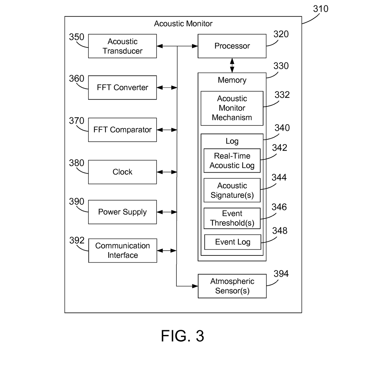
[0026]The disclosure and claims herein relate to an acoustic monitor that detects and logs events based on the acoustic characteristics of the event. The acoustic monitor is placed on a tower, and a baseline acoustic signature is established. Events can be defined by variance from the baseline, or by matching one of a set of predefined acoustic signatures. When an event is detected, the acoustic monitor logs the event. A repair person queries the acoustic monitors to narrow down where the event occurred to be between two towers, and can then query the acoustic monitors on those two towers. Using the timestamps of the event in each of the towers, and using the known speed of sound in air, the repair person can quickly calculate the location of the event from both towers. By knowing the location of the event, the repair person knows exactly how to quickly access the location to make the needed repairs.

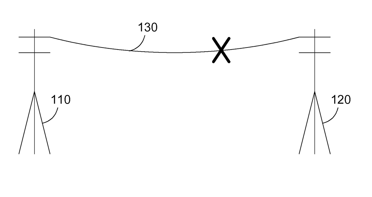
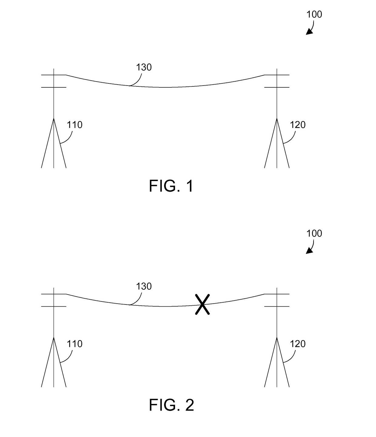
[0027]FIG. 1 represents a power transmission system 100 that includes two towers 110...


PUM


Abstract

An acoustic monitor detects and logs events based on the acoustic characteristics of the event. The acoustic monitor is placed on a power transmission tower, and a baseline acoustic signature is established. Events can be defined by variance from the baseline, or by matching one of a set of predefined acoustic signatures. When an event is detected, the acoustic monitor logs the event. A repair person queries the acoustic monitors to narrow down where the event occurred to be between two towers, and can then query the acoustic monitors on those two towers. Using the timestamps of the event in each of the towers, and using the known speed of sound in air, the repair person can quickly calculate the location of the event from both towers. By knowing the location of the event, the repair person knows exactly how to quickly access the location to make the needed repairs.

Description

BACKGROUND[0001]1. Technical Field[0002]This disclosure generally relates to power distribution systems, and more specifically relates to a way to detect a failure in power transmission lines.[0003]2. Background Art[0004]High-voltage power transmission lines often span long distances between towers. These transmission lines and their towers may be located in remote areas. In addition, towers in some areas, such as mountainous areas, may make access to the power lines and towers difficult for making needed repairs.[0005]Power transmission lines can fail due to several different types of events. An ice storm can deposit so much ice on a power transmission line that the additional weight of the ice causes the power transmission line to break. A vandal or saboteur can cause a power line to break by placing a conductor, such as a chain or metal bar, on a power transmission line to create a short to ground or between power transmission lines. The high current created by such a short can c...

Claims


Application Information

Patent Timeline
IPC IPC(8): G01N29/46G01N29/38G01R31/08
CPCG01N29/46G01R31/088G01N2291/0289G01N29/38G01N2291/023G01R31/085G01R31/1209G01N29/4436G01N29/4454G01N2291/2626G01N2291/2697
Inventor CHANTZ, HYMAN D.
Owner KYNDRYL INC
Learn More