Distortion-corrected magnetic resonance measurement and magnetic resonance device

Inactive Publication Date: 2005-02-17
SIEMENS HEALTHCARE GMBH
View PDF6 Cites 7 Cited by
  • Summary
  • Abstract
  • Description
  • Claims
  • Application Information

AI Technical Summary

Benefits of technology

[0016] The advantage of the method is that, depending on the distortion correction algorithm used and the coefficients used to describe the magnetic field, the magnetic resonance measurement can be performed in each case in one measurement area, where the measurement area always allows an optimum correction of the examination area. In this way optimum distortion-corrected magnetic resonance images can be created. A requirement for this is that, because the coefficients and the correction algorithm are known, it is possible even before the measurement of the examination area to make a statement about the overall measurement area required for complete correction. Thus additionally needed areas can be measured as well and the user obtains after measurement an optimally corrected magnetic resonance image of the examination area which does not exhibit any black image areas as a result of correction.
[0020] With the aid of the assignment the necessary measurement area can be calculated beforehand during layer planning in the examination area and displayed to the user. With the aid of the method the user can measure fully distortion-corrected images without missing information in the edge areas.
[0023] In an especially fast embodiment of the method, the measurement area is determined by way of the assignment of the correction algorithm starting from picture elements on a surrounding edge of the examination area. This has the advantage that the large number of picture elements of which lie within the examination area and thus need no additional measurement picture elements are not included for determining the measurement area. Accordingly the measurement area is calculated much more quickly. Accordingly a new calculation can be performed for each measurement and the assignment plan does not have to be created beforehand for the entire examination area.
[0025] In a further development of the method the operator has the opportunity of activating or deactivating a distortion correction in accordance with an embodiment of the invention in the magnetic resonance device. This last feature has the advantage that the operator, if he does not need the additional information obtained by distortion correction, can switch this feature off and thus obtain magnetic resonance images more quickly.

Problems solved by technology

If there are inhomogeneities of the magnetic field present within the imaging volume of the magnetic resonance device, these lead to geometrical distortions of the magnetic resonance image.
With the method of distortion correction described the problem arises whereby, for correction of the picture elements which lie at the edge of the examination area it is often not possible to perform a complete correction since the image information required for correction lies outside the examination area recorded.

Method used


Image

  • Distortion-corrected magnetic resonance measurement and magnetic resonance device
  • Distortion-corrected magnetic resonance measurement and magnetic resonance device
  • Distortion-corrected magnetic resonance measurement and magnetic resonance device

Examples


Embodiment Construction

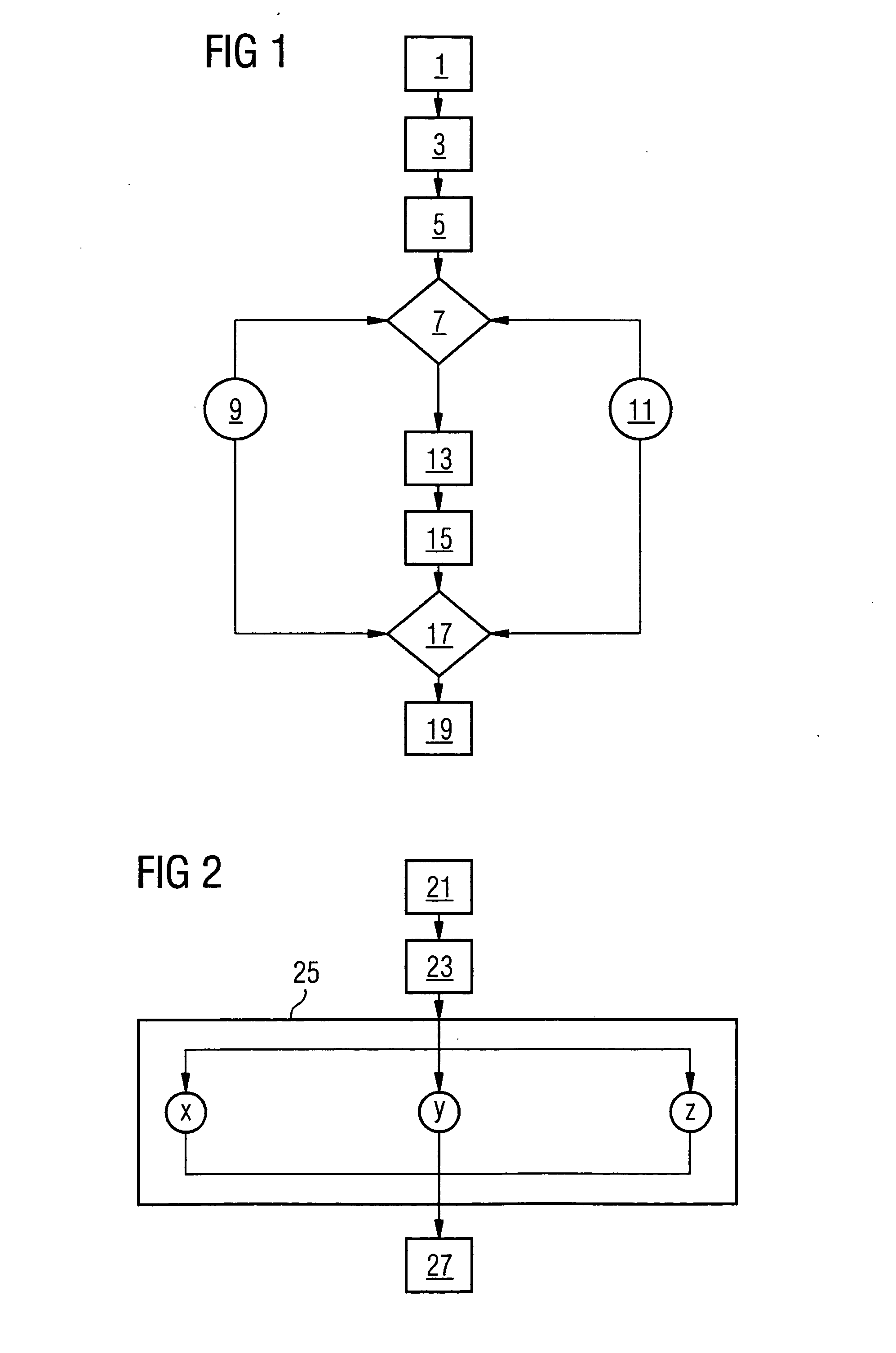
[0033]FIG. 1 shows a typical execution sequence of the method in accordance with an embodiment of the invention for performing a distortion-corrected magnetic resonance examination. After a patient is registered, positioned and brought into 1 a magnetic resonance device a localizer measurement 3 is normally performed. The localizer measurement 3 gives the operator an overview of the position of the patient within the magnetic resonance device, in which case the localizer measurement is normally taken at low resolution. The examination area is determined 5 on the basis of the localizer measurement 3. The area of examination is the area of interest which is needed to resolve a clinical inquiry.

[0034] The next stage is the calculation 7 of the measurement volume. Input parameters are the examination area, the distortion correction algorithm used 9 and also the coefficients used 11 to describe the magnetic field used in the measurement. For example a distortion field of the magnetic fi...


PUM


Abstract

A distortion-corrected magnetic resonance examination with a magnetic resonance device is undertaken by use of a distortion correction algorithm which uses coefficients to describe a magnetic field used in a measurement. In this case, after an examination area has been selected, by including the distortion correction algorithm and the coefficients for description of the magnetic field, a measurement area needed for correction is determined. Subsequently a magnetic resonance measurement is performed in the measurement area. Subsequently a distortion-corrected magnetic resonance image of the examination area is created with the aid of the distortion correction algorithm. In addition to the examination area, the measurement area and also any necessary measurement times can be shown on a display of the magnetic resonance device. This type of magnetic resonance examination does not include in the magnetic resonance image any picture elements which were not measured because of distortion.

Description

[0001] The present application hereby claims priority under 35 U.S.C. §119 on German patent application number DE 103 37 241.5 filed Aug. 13, 2003, the entire contents of which are hereby incorporated herein by reference. FIELD OF THE INVENTION [0002] The invention generally relates to a method for executing a distortion-corrected magnetic resonance examination on a magnetic resonance device. Preferably, it relates to a method that does this by way of a distortion correction algorithm which uses coefficients to describe a magnetic field used in the measurement. [0003] The invention also generally relates to a magnetic resonance device for executing the method. BACKGROUND OF THE INVENTION [0004] Magnetic resonance technology is a known technology for obtaining images of the inside of the body of an object under examination. It does this by radiating high-frequency signals from a high-frequency system into the object to be investigated such that magnetic resonance signals are emitted ...

Claims


Application Information

Patent Timeline
IPC IPC(8): G01R33/565
CPCG01R33/56518G01R33/56563
Inventor CANDA, VALERKRIEG, ROBERTSCHRECK, OLIVER
Owner SIEMENS HEALTHCARE GMBH
Why Eureka
Try Eureka