
Fluorescence lifetime measurement device for analyzing multi-exponential decay function type experimental data at high speed and measurement method therefor

a multi-exponential decay function and measurement device technology, applied in the field of fluorescence lifetime measurement apparatus and fluorescence lifetime measurement method, can solve the problems of signal loss, tcspc basically has a restriction on measurement time, and high-gain photodetectors have a problem of transit time spread in terms of operation, so as to achieve the effect of accelerating the calculation of fluorescence lifetime values of samples

Active Publication Date: 2020-03-19
IND ACADEMIC CORP FOUND YONSEI UNIV +1
View PDF0 Cites 2 Cited by
  • Summary
  • Abstract
  • Description
  • Claims
  • Application Information

AI Technical Summary

Benefits of technology

The patent text describes a way to quickly calculate the lifespan of fluorescence in a mixture of samples that have different fluorescence lifetimes. This allows for the analysis of the samples more quickly.

Problems solved by technology

However, the high-gain photodetector has a problem of transit time spread (TTS) in terms of operation principle.
However, TCSPC basically has a restriction on measurement time in a single photon counting method.
If two or more photons are detected by the counter within a measurement cycle, particularly if arrival times of two photons are too close to be split into two pulses, the counter counts only a value of a photon arriving first, such that signal loss occurs, resulting in a shorter fluorescence lifetime than an actual value.
Further, even in a single photon, if a plurality of samples having two or more different fluorescence lifetimes are mixed, there may be many more problems in measuring fluorescence lifetimes independently.
However, the non-linear least square curve fitting method uses a repetitive algorithm which compares a model function with the measured data by repeatedly adjusting parameters until a difference between the model function and the measured data becomes a minimum.
If a difference between the model function and the measured data is less than a given tolerance condition, the non-linear least square curve fitting method terminates calculation, such that there is a disadvantage in that the method may obtain only approximate values of parameters.
Further, the algorithm is an algorithm which repeats calculations until the tolerance condition is satisfied, thus leading to a great number of computations for obtaining a desired value.
In the case of MRI or FILM equipment for image configuration, it is required to analyze multiple fluorescence signals of hundreds of thousands to millions of pixels constituting a two-dimensional or three-dimensional image, such that there is a drawback in that a computation time for completing the entire image is very long.

Method used


Image

  • Fluorescence lifetime measurement device for analyzing multi-exponential decay function type experimental data at high speed and measurement method therefor
  • Fluorescence lifetime measurement device for analyzing multi-exponential decay function type experimental data at high speed and measurement method therefor

Examples


Embodiment Construction

[0014]Advantages and features of the present invention and methods of accomplishing the same may be understood more readily by reference to the following detailed description of exemplary embodiments and accompanying drawings. The present invention may, however, be embodied in many different forms and should not be construed as being limited to the embodiments set forth herein. Rather, these embodiments are provided so that this disclosure will be thorough and complete and will fully convey the concept of the invention to those skilled in the art, and the present invention will only be defined by the appended claims.

[0015]Unless otherwise defined, all terms (including technical and scientific terms) used herein have the same meaning as commonly understood by one of ordinary skill in the art to which this invention belongs. It will be further understood that terms, such as those defined in commonly used dictionaries, should be interpreted as having a meaning that is consistent with t...


PUM


Abstract

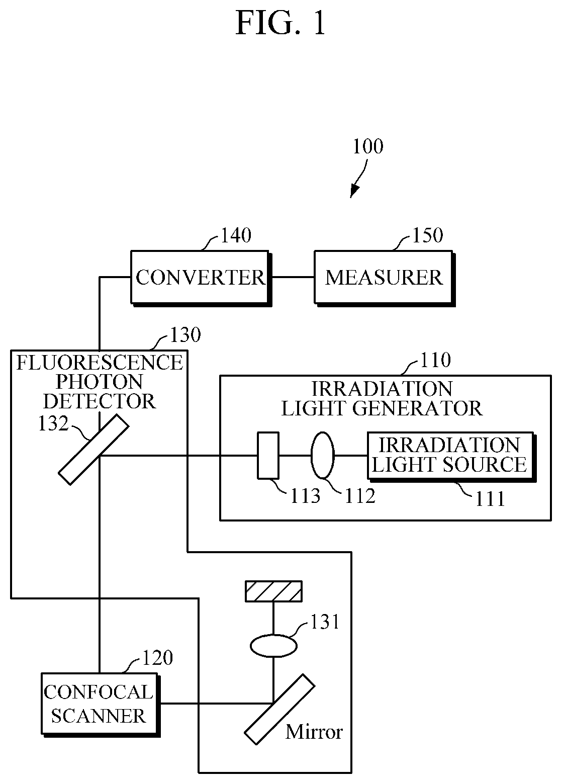
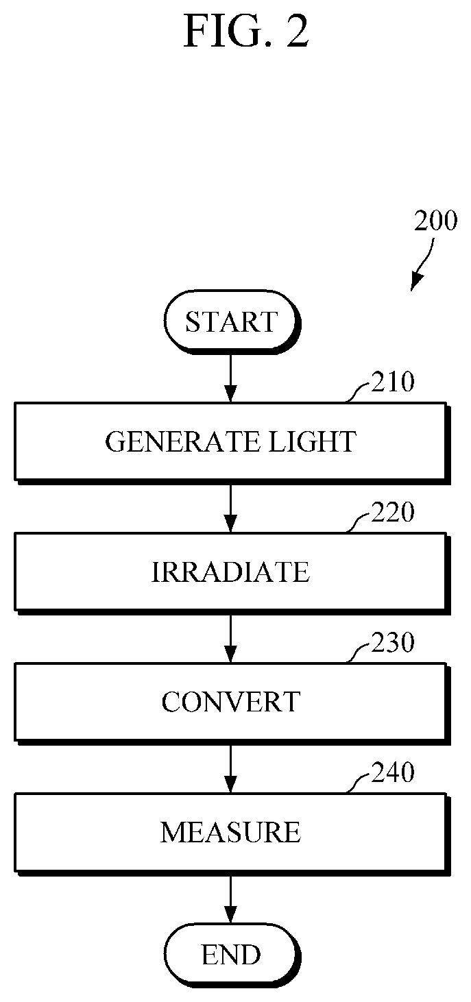
A fluorescence lifetime measuring apparatus according to an embodiment of the present invention includes: an irradiation light generator configured to generate irradiation light; a fluorescence photon detector configured to irradiate at least one or more samples, containing fluorescent molecules, with the irradiation light and collect a fluorescence photon generated by the irradiation; a converter configured to amplify the fluorescence photon and convert the amplified fluorescence photon into a fluorescence signal; and a measurer configured to analyze data of a function of the fluorescence signal by using a function obtained by multiplying a value, which is obtained by integrating the function of the fluorescence signal, by a simulation function.

Description

TECHNICAL FIELD[0001]The following description relates to a fluorescence lifetime measuring apparatus and a fluorescence lifetime measuring method for measuring fluorescence lifetimes, and more particularly to a fluorescence lifetime measuring apparatus and a fluorescence lifetime measuring method, which may independently measure the fluorescence lifetimes for two or more mixed samples with a minimum time.BACKGROUND ART[0002]Microscopes are divided into a first-generation optical microscope, a second-generation electron microscope, and a third-generation scanning probe microscope, and are used in a wide variety of applications such as medicine, molecular biology, development of new pharmaceuticals, and material engineering.[0003]However, a fluorescence lifetime imaging microscope is now emerging as a key technique in the research of microscopes. The fluorescence lifetime imaging microscope is equipment (FLIM-FRET) which most accurately measures Fluorescence Resonance Energy Transfer...

Claims


Application Information

Patent Timeline
IPC IPC(8): G01N21/64G06T5/00A61B5/00
CPCG01N21/6408G01N21/6458G06T2207/30024G06T2207/10064A61B5/0059G06T5/008G02B21/0076G02B21/082G06T5/94
Inventor KIM, DUG YOUNGHWANG, WON SANGKIM, DONG EUNKANG, MIN GU
Owner IND ACADEMIC CORP FOUND YONSEI UNIV
Learn More