Controller for buck dc/dc converter with effective decoupling

a controller and converter technology, applied in the direction of electric variable regulation, process and machine control, instruments, etc., can solve the problems of load current or voltage disturbance, negatively affecting the power quality of the buck dc-dc converter

Active Publication Date: 2020-03-19
HAMILTON SUNDSTRAND CORP
View PDF0 Cites 1 Cited by
  • Summary
  • Abstract
  • Description
  • Claims
  • Application Information

AI Technical Summary

Problems solved by technology

In addition, when one or more loads are added, removed, or adjusted, a load current or voltage disturbance can occur.
The output voltage or DC link input voltage can be affected by disturbances in the respective DC link input voltage and / or load, negatively affecting the power quality of the buck DC-DC converter.

Method used


Image

  • Controller for buck dc/dc converter with effective decoupling
  • Controller for buck dc/dc converter with effective decoupling
  • Controller for buck dc/dc converter with effective decoupling

Examples


first embodiment

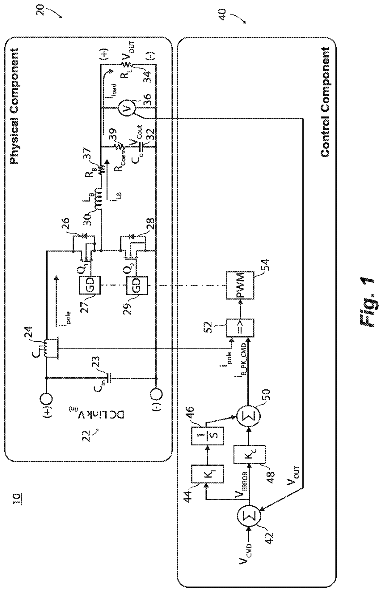
[0032]Reference will now be made to the drawings wherein like reference numerals identify similar structural features or aspects of the subject disclosure. For purposes of explanation and illustration, and not limitation, a block diagram of an exemplary embodiment of a buck DC-DC converter in accordance with the disclosure is shown in FIG. 1 and is designated generally by reference character 10. Converter 10 includes a physical component 20 and a control component 40.

[0033]Those skilled in the art will readily appreciate that other configurations of the physical component 20 correspond to different topologies that can be used in a similar way without departing from the scope of this disclosure such as an asynchronous buck converter that uses a diode instead of a second switch.

[0034]The physical component 20 includes a DC link input voltage (Vin) 22, a DC link capacitor 23 (having capacitance Cin), a current transformer (CT1) 24 provided at a first node , a first switch (Q1) 26, a se...

second embodiment

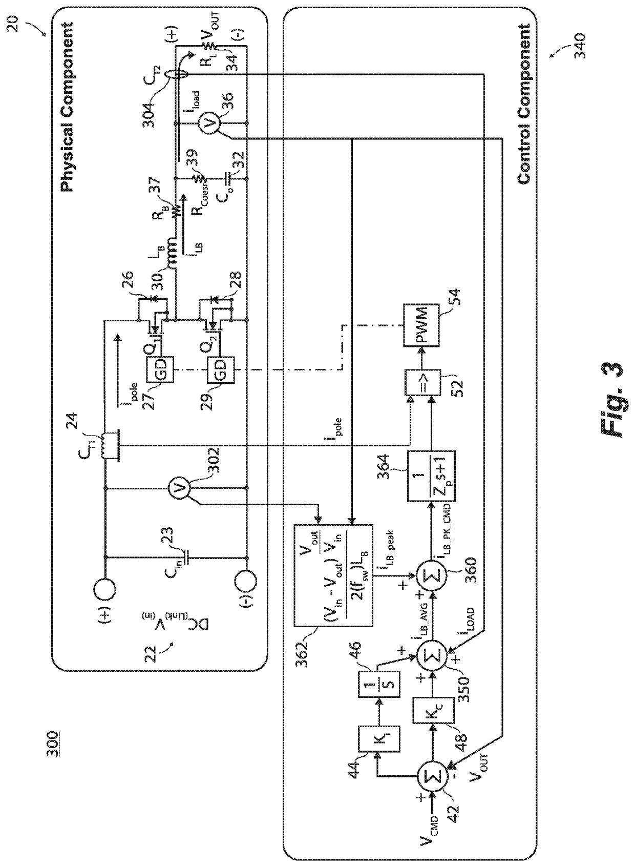
[0051]For purposes of explanation and illustration, and not limitation, a block diagram of an exemplary embodiment of a buck DC-DC converter in accordance with the disclosure is shown in FIG. 3 and is designated generally by reference character 300.

[0052]Methods associated with operation of the converter 300 in accordance with the disclosure, or aspects thereof, are provided in FIGS. 3-5, as will be described. The systems and methods described herein can be used to provide improved dynamic stiffness.

[0053]Converter 300 is configured to include the physical component 20 as described with respect to converter 10 shown in FIG. 1, and a control component 340 that improves dynamic stiffness of the converter 100 relative to the dynamic stiffness of converter 10. The physical component 20 includes the same elements as those shown in the physical component 20 of converter 10 shown in FIG. 1, whereas the elements can have the same or similar structures and functions as described with respect...


PUM


Abstract

A DC-DC power converter, a control component of a DC-DC power converter, and a method of controlling a buck DC-DC power converter are provided. The method includes receiving at least one of a measured load current and a measured input voltage. The measured load current is a measurement of current that flows from the buck inductor of a physical component of the buck DC-DC power converter. The measured input voltage is a measurement of the DC link input voltage measured across a DC link of the physical component of the buck DC-DC power converter. The method further includes generating a control signal to control a pulse width modulator (PWM), wherein the control signal is based on at least one of the measured load current and the measured input voltage. The PWM is configured to control at least one switch that is coupled to the buck inductor to allow the buck inductor to operate on a current flowing from the DC link only when the at least one switch is turned ON.

Description

BACKGROUND OF THE INVENTION1. Field of the Invention[0001]The present disclosure relates to buck DC-DC converters, and more particularly, to a controller of a buck DC-DC converter that effectively decouples disturbances in a load current or voltage or an input voltage provided by a high voltage DC link from the other of the DC link input voltage and the load current or voltage.2. Description of Related Art[0002]Buck DC-DC converters are configured to convert a high voltage to a lower voltage. A physical component that steps down the input voltage to a lower average output voltage. This function is implemented with an inductor, capacitor, and one or more switches. The physical component is controlled by a control algorithm that can be implemented by firmware, software executed by a hardware processor, and / or analog discrete components, which can be implemented, for example using a field programmable gate array (FPGA) or software digital signal processor (DSP). In applications, the hi...

Claims


Application Information

Patent Timeline
Patent Type & Authority Applications(United States)
IPC IPC(8): H02M3/158
CPCH02M3/1582H02M3/1588H02M3/158H02M1/0022H02M1/0019Y02B70/10H02M3/156H02M1/08
Inventor SAGONA, JOHN DUWARD
Owner HAMILTON SUNDSTRAND CORP
Why Eureka
Try Eureka