Multi-directional input device

a multi-directional input and input device technology, applied in the direction of mechanical control devices, manual control with single controlling member, instruments, etc., can solve the problems of difficult to provide sufficient strength to the snap-engaging portion between the operation shaft and the lower arm, and become difficult to reduce the entire height of the device, so as to reduce the strength of the operation shaft and the lower arm, and reduce the height of the device. , the effect of increasing the degree of freedom in the shape of the lower arm

Active Publication Date: 2020-03-26
HOSIDEN CORP
View PDF3 Cites 6 Cited by
  • Summary
  • Abstract
  • Description
  • Claims
  • Application Information

AI Technical Summary

Benefits of technology

[0006]The present invention has been made in view of the problems as described above, and an object of the present invention is to provide a multi-directional input device, in which the entire height of the device can be reduced even when the rotation radius of an operation shaft is increased and the device can be downsized without lowering the strength of the operation shaft and a lower arm.
[0011]According to the present invention, an upward convex spherical trapezoidal portion whose diameter decreases upward is provided at the lower end of the operation shaft projecting downward of the lower arm, and the receiving portion for the upward convex spherical trapezoidal portion is provided in the case. The receiving portion has a receiving surface that is configured with a spherical surface having the same radius of curvature as the radius of curvature of the spherical zone of the upwardly convex spherical trapezoidal portion, the receiving surface against which a spherical zone of the upward convex spherical trapezoidal portion is pressed from downward by the compression coil spring. The operation shaft is supported to be rotatable about the curvature center of the receiving surface. In this manner, since the operation shaft is supported to be rotatable about the curvature center of the receiving surface of the receiving portion while being prevented from coming off by the receiving portion positioned downward of the lower arm, the entire height of the device is reduced even if the rotation radius of the operation shaft is increased, and the device can be downsized without lowering the strength of the operation shaft and the lower arm.
[0012]Further, the actuating member is supported by the lower end of the operation shaft in a state in which the rotation around an axis of the operation shaft is regulated, and is provided with a protrusion projecting radially outward from an upper end of the downward convex spherical trapezoidal portion. The protrusion is inserted so as to be movable vertically in a guide groove that extends in a vertical direction on an inner wall of the case, so that rotation around an axis of the operation shaft of the actuating member is regulated. In this manner, rotation around an axis of the operation shaft is regulated via the actuating member. Therefore, degree of freedom in a shape of the lower arm is increased, the lower arm can be downsized, and the device can be downsized.
[0013]Further, an upward convex spherical trapezoidal portion whose diameter decreases upward is provided at the lower end portion of the operation shaft projecting downward of the lower arm, and a receiving portion for the upward convex spherical trapezoidal portion is provided in the case. The receiving portion has a receiving surface that is configured with a spherical surface having the same radius of curvature as radius of curvature of a spherical zone of the upward convex spherical trapezoidal portion, the receiving surface against which a spherical zone of the upward convex spherical trapezoidal portion is pressed from downward by the compression coil spring. The operation shaft is supported so as to be rotatable about the center of curvature of the receiving surface. The lower arm has a curved upper surface provided along a cylindrical surface arranged coaxially on one horizontal axis that passes through the center of curvature of the receiving surface and extends in a moving direction of the lower arm. The operation shaft is provided with an engaging portion with the lower arm. The engaging portion has a downward engaging surface that is curved along the curved upper surface of the lower arm and is movable on the curved upper surface of the lower arm when the operation shaft rotates. In this manner, the operation shaft in a state of being inserted through an elongated hole of the lower arm from downward is rotated by 90° so that a downward engaging surface of the engaging portion of the operation shaft is arranged to face the curved upper surface of the lower arm for assembly. Accordingly, the operation shaft and the lower arm can be provided with enough strength, and the device can be downsized without lowering of the strength of the operation shaft and the lower arm.
[0014]Further, the pusher supported movably in the vertical direction and the pressing switch for detecting the pressing movement of the operation shaft are further included in the case, the lower arm moving downward with the pressing movement of the operation shaft moves downward the pusher, and the pressing switch is operated via the pusher. In this manner, before the pusher is incorporated, the lower arm has degree of freedom in a downward direction, and there is no possibility of interference between the downward engaging surfaces of the engaging portions of the operation shaft and the curved upper surface of the lower arm even if the operation shaft is rotated by 90° and assembled. For this reason, a gap (clearance) between the downward engaging surface of the engaging portion of the operation shaft and the curved upper surface of the lower arm can sufficiently be reduced, and the pressing switch can be operated with a short stroke.

Problems solved by technology

However, in the conventional multi-directional input device as described above, since the snap-engaging portion between the operation shaft and the lower arm serves as a rotation center of the operation shaft, it becomes difficult to reduce the entire height of the device when the rotation radius of the operation shaft is increased.
Further, in order to ensure the assemblability, it is difficult to provide sufficient strength to the snap-engaging portion between the operation shaft and the lower arm.

Method used


Image

  • Multi-directional input device
  • Multi-directional input device
  • Multi-directional input device

Examples


Embodiment Construction

[0032]Hereinafter, a multi-directional input device according to an embodiment of the present invention will be described based on the drawings.

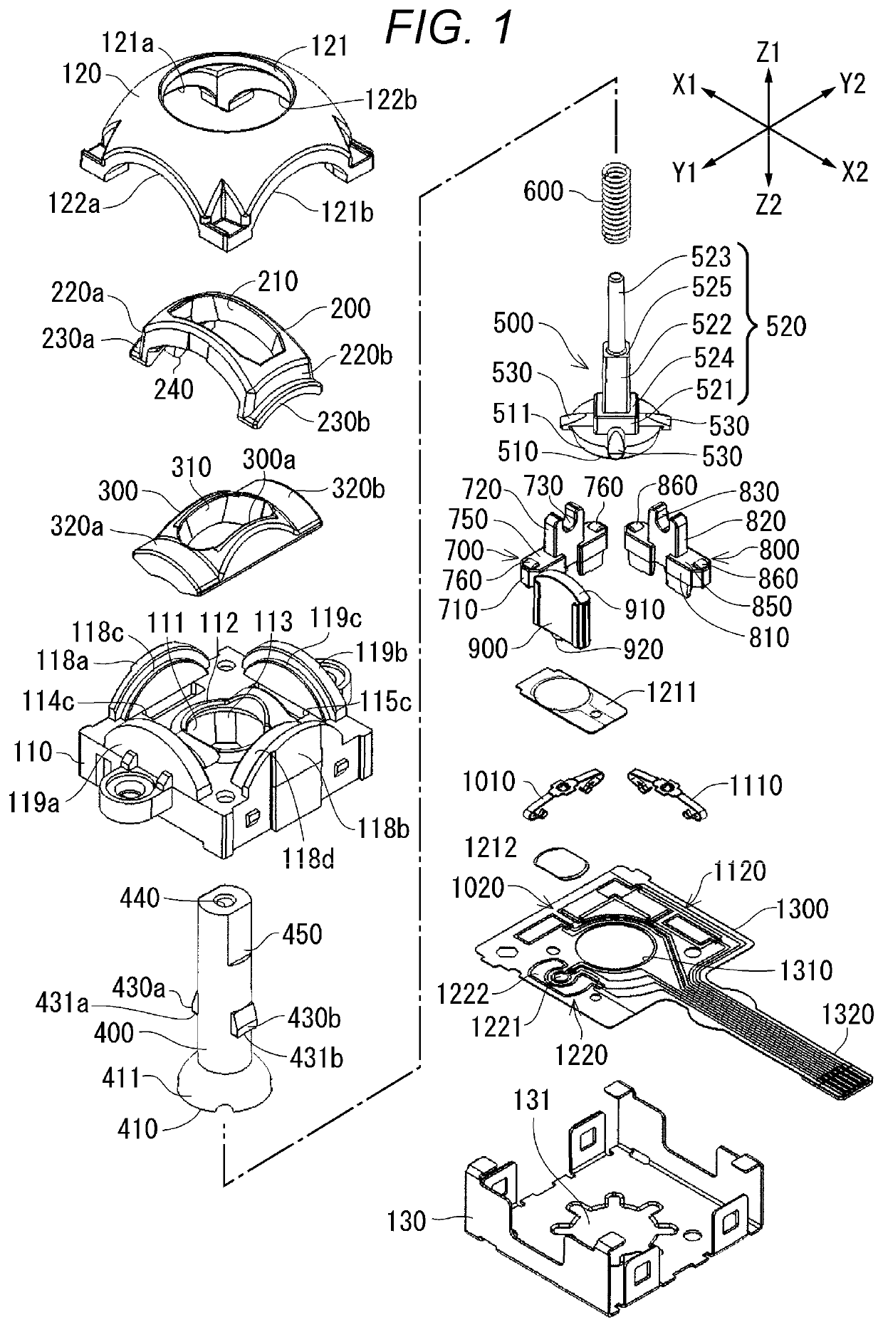
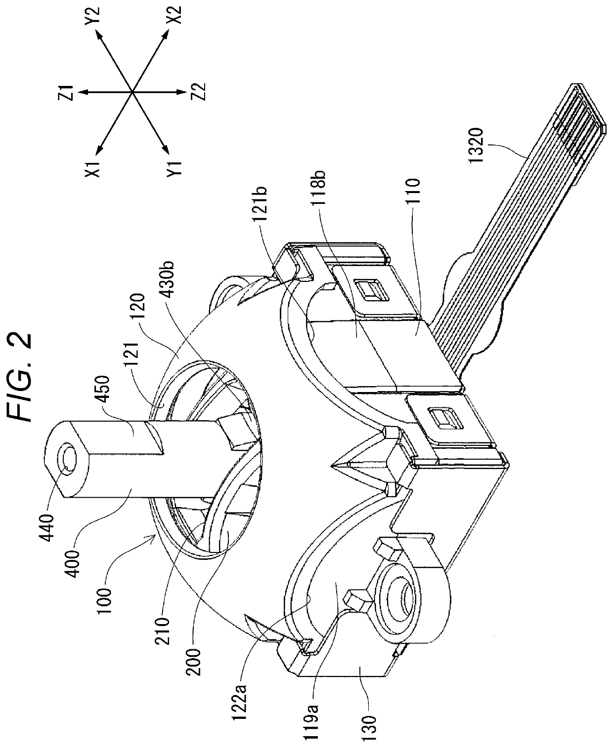
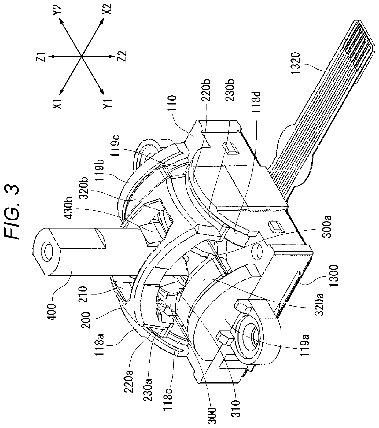
[0033]As shown in FIGS. 1 to 17, the multi-directional input device according to the embodiment of the present invention includes a case 100, a pair of upper and lower arms 200 and 300, an operation shaft 400, an actuating member 500, a compression coil spring 600, first and second sliders 700 and 800, a pusher 900, first and second variable resistors 1000 and 1100 which are first and second electric components, a pressing switch 1200 which is a third electric component, and a substrate 1300.

[0034]In coordinate axes shown in FIGS. 1 to 17, a Y1-Y2 direction is a front-rear direction (depth direction) of the multi-directional input device, an X1-X2 direction is a lateral direction (width direction) of the multi-directional input device, and a Z1-Z2 direction is a vertical direction (height direction) of the multi-directional input device. The...


PUM


Abstract

In a multi-directional input device, an upward convex spherical trapezoidal portion is provided at a lower end of an operation shaft projecting downward of a lower arm, a receiving portion for the upward convex spherical trapezoidal portion is provided in a case, the receiving portion has a receiving surface configured with a spherical surface having a radius of curvature identical to a radius of curvature of a spherical zone of the upward convex spherical trapezoidal portion, the receiving surface against which the spherical zone of the upward convex spherical trapezoidal portion is pressed downward by a compression coil spring, and the operation shaft is supported to be rotatable around the center of curvature of the receiving surface.

Description

BACKGROUND OF THE INVENTION(1) Field of the Invention[0001]The present invention relates to a multi-directional input device.(2) Description of Related Art[0002]As shown in JP 2000-112552 A, a conventional multi-directional input device includes a case, a pair of upper and lower arms, an operation shaft, an actuating member, a compression coil spring, and a plurality of electric components. The case has a bottom plate. The pair of upper and lower arms are movably supported in two directions orthogonal to each other in the case, and each has an elongated hole extending in a direction orthogonal to a moving direction. The operation shaft is rotatable in a state of passing through each elongated hole. The actuating member is movably supported in an axial direction of the operation shaft at a lower end of the operation shaft projecting downward of the lower arm, and is provided with a downward convex spherical trapezoidal portion whose diameter decreases downward. The compression coil s...

Claims


Application Information

Patent Timeline
Patent Type & Authority Applications(United States)
IPC IPC(8): G05G9/047H01C10/16
CPCH01C10/16G05G9/047G05G2009/04711G05G2009/04751G05G2009/04744G05G2009/04777H01H25/04H01H25/008
Inventor ASANO, MITSUHIRO
Owner HOSIDEN CORP
Why Eureka
Try Eureka