
Sliding scale release for an automatically opening tool

Active Publication Date: 2020-04-02
HALUCHA WALTER +1
View PDF0 Cites 10 Cited by
  • Summary
  • Abstract
  • Description
  • Claims
  • Application Information

AI Technical Summary

Benefits of technology

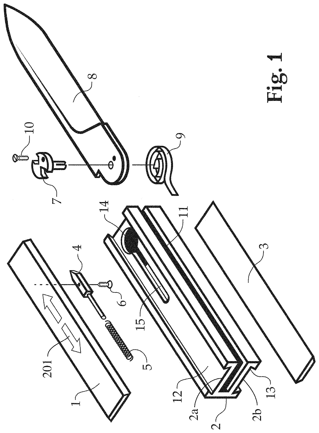
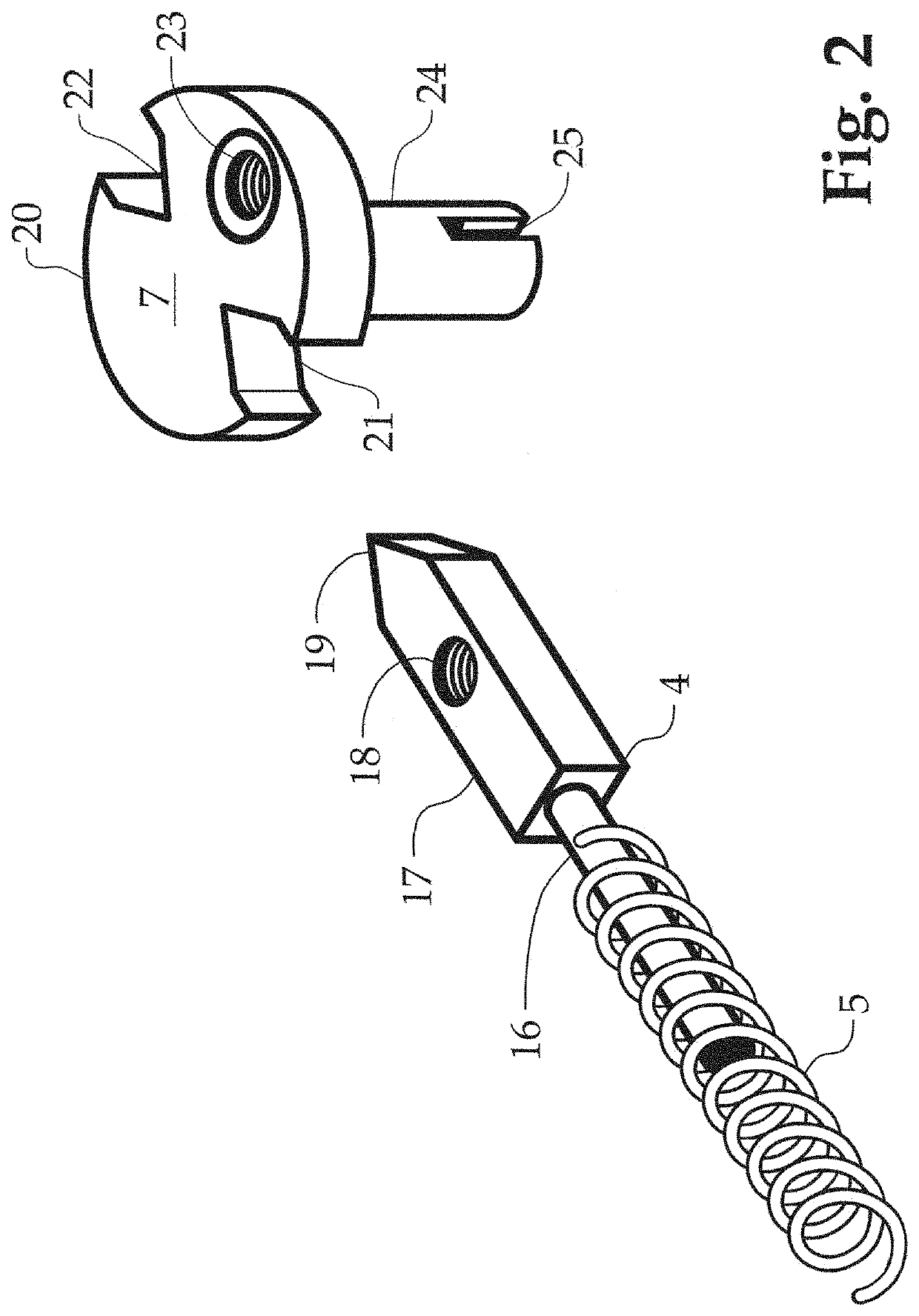
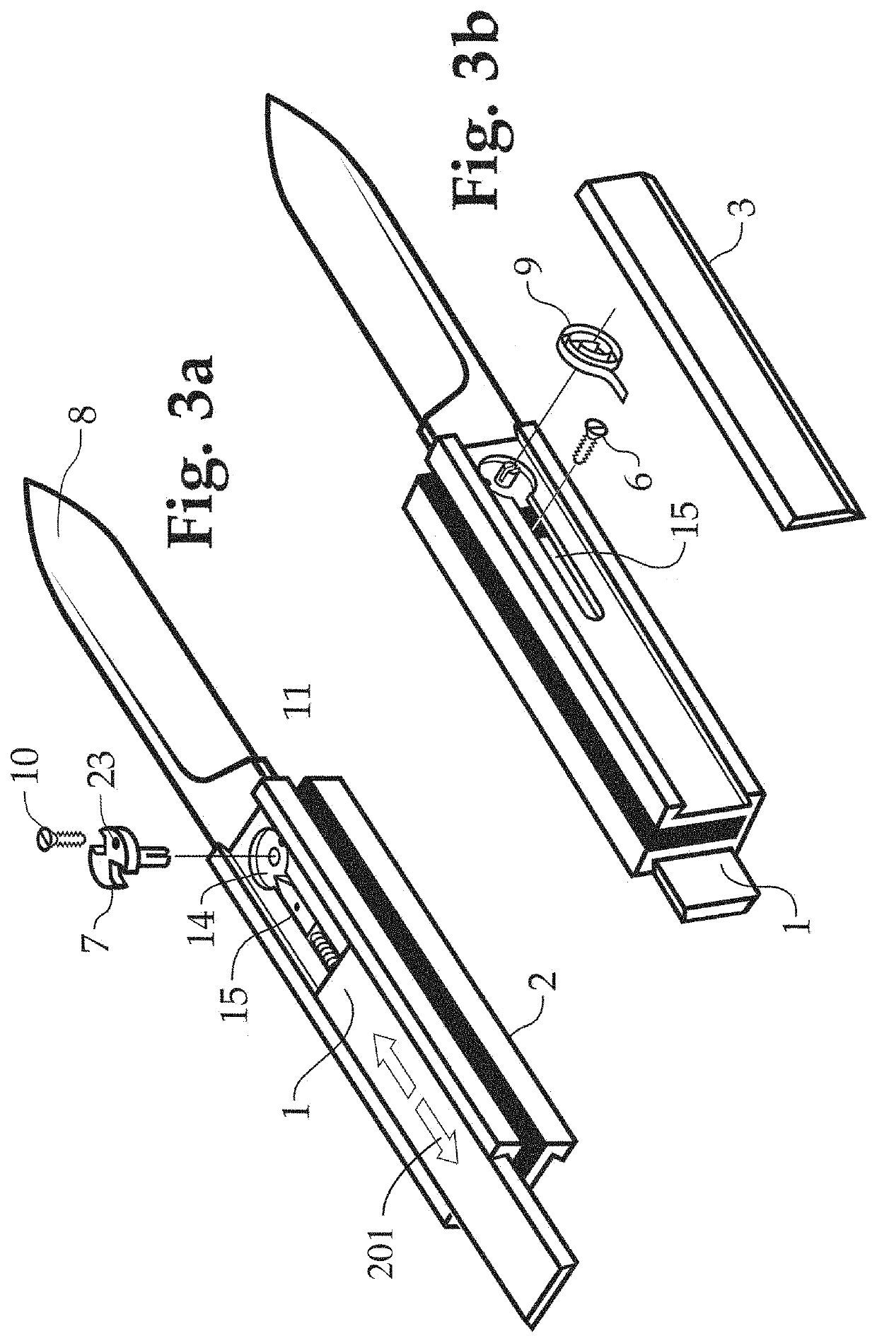
The present invention provides an automatically opening tool with a sliding scale and a knife or other tool that can be used for both right-hand and left-hand use. The tool has a frame with two side walls and a gap between them to receive the tool. The tool can swing out the bottom of the cavity or extend and retract. The sliding scale can be moved in the distal-proximal / north-south direction along the longitudinal axis of the tool to activate the release of the automatically opening feature. The tool can be locked in the closed position and resiliently urged in the distal direction to lock the tool back in the closed position. The handle features an internal design that is sleek and without visible fasteners. The blade locking device can include a chisel point sear that can force the blade to come to battery or precisely stop in position with low wiggle or play. The parts can be easily disassembled and reassembled by the user, as opposed to a factory permanent pinned assembly. The internal parts are configured to allow for easy interchangeability of parts and can be used in any blade or other tool size and external profile appearance.

Problems solved by technology

This makes them inconvenient for users to service or reconfigure.
The resulting tolerance fit leave micro-gaps in the machinery that have a cumulative effect resulting in potential blade wiggle in either open or closed positions.
This is observable in surviving Flylock style knives manufactured in the early 1900's, and also in modern knives, as part surfaces wear with age, increasing the loose play in an “locked” blade.
In addition to the complexity of conventional mechanisms, the appearance of these mechanisms can be undesirable.
For example, buttons and levers can be unsightly.
They can also be difficult to manipulate under certain circumstances.

Method used


Image

  • Sliding scale release for an automatically opening tool
  • Sliding scale release for an automatically opening tool
  • Sliding scale release for an automatically opening tool

Examples


Embodiment Construction

[0047]The present disclosure may be understood more readily by reference to the following detailed description of the disclosure taken in connection with the accompanying drawing figures, which form a part of this disclosure. It is to be understood that this disclosure is not limited to the specific devices, methods, conditions or parameters described and / or shown herein, and that the terminology used herein is for the purpose of describing particular embodiments by way of example only and is not intended to be limiting of the claimed disclosure.

[0048]Also, as used in the specification and including the appended claims, the singular forms “a,”“an,” and “the” include the plural, and reference to a particular numerical value includes at least that particular value, unless the context clearly dictates otherwise. Ranges may be expressed herein as from “about” or “approximately” one particular value and / or to “about” or “approximately” another particular value. When such a range is expre...


PUM

PropertyMeasurementUnit
Diameteraaaaaaaaaa
Heightaaaaaaaaaa

Abstract

An automatically opening tool with sliding scale release, including a frame; a tool; a release mechanism attached to the tool; a biasing mechanism for extending the tool; and a scale coupled to the frame and release mechanism. The tool is constructed such that sliding the scale along the longitudinal axis automatically unlocks the tool from the extended or retracted configurations. The tool can open automatically or manually. The tool can swing open or extend out a front opening in the frame.

Description

CROSS REFERENCE TO RELATED APPLICATIONS[0001]This application claims priority to Ser. No. 15 / 792,204, filed Oct. 24, 2017, and to provisional application Ser. No. 62 / 436,570, filed Dec. 20, 2016. The entire contents of these applications are incorporated herein by reference.BACKGROUND[0002]The invention relates generally to automatically opening tools, such as knives, which can be opened with the activation of a release.[0003]Automatic knives and other tools, e.g., with spring biased blades have a variety of configurations and release button designs. For example, some knives have a reciprocating (sliding) button and are referred to as having Flylock mechanisms. Existing Flylock sliding buttons generally move along the long longitudinal length axis of the knife, within an opening in a distal portion of the handle. As used herein, for purposes of reference only, an open knife will be referred to as oriented with the free tip of the blade at the distal end and its blade edge facing upw...

Claims


Application Information

Patent Timeline
IPC IPC(8): B26B5/00B24B3/60A45D24/06B67B7/04
CPCB24B3/607B25B23/16B67B7/04B26B5/00A45D24/06B25B15/00
Inventor HALUCHA, WALTER
Owner HALUCHA WALTER
Learn More