
Bearing arrangement for a wind turbine, wind turbine and method for manufacturing a wind turbine

a technology for wind turbines and bearings, which is applied in the direction of shafts, motors, wind energy generation, etc., can solve the problems of weak bending of the main shaft around the horizontal axis, difficult access to bearings and corresponding seals, and substantial loads on the main sha

Inactive Publication Date: 2020-04-02
SIEMENS GAMESA RENEWABLE ENERGY AS
View PDF0 Cites 1 Cited by
  • Summary
  • Abstract
  • Description
  • Claims
  • Application Information

AI Technical Summary

Benefits of technology

The patent text describes a bearing arrangement with a support structure that increases the stiffness in bending about a horizontal axis perpendicular to the shaft axis. This arrangement transfers all rotor bending loads to the bed frame. The use of stainless steel or high alloy steel reduces the risk of fretting and eliminates the need for additional coatings or sleeves. The technical effects of this patent text are increased flexibility and durability of the bearing arrangement and reduced risk of damage to the bearing components.

Problems solved by technology

The main shaft is subjected to substantial loads during the operation or the wind turbine.
Disadvantages associated with the first configuration are that it is weak in bending around a horizontal axis running at right angles with respect to the axis of rotation of the main shaft.
The second configuration is disadvantageous in that it is difficult to access the bearings and corresponding seals, for example, for maintenance purposes.
Such radial openings may reduce the weight of the support structure, while only marginally reducing its bending stiffness.

Method used


Image

  • Bearing arrangement for a wind turbine, wind turbine and method for manufacturing a wind turbine
  • Bearing arrangement for a wind turbine, wind turbine and method for manufacturing a wind turbine
  • Bearing arrangement for a wind turbine, wind turbine and method for manufacturing a wind turbine

Examples


Embodiment Construction

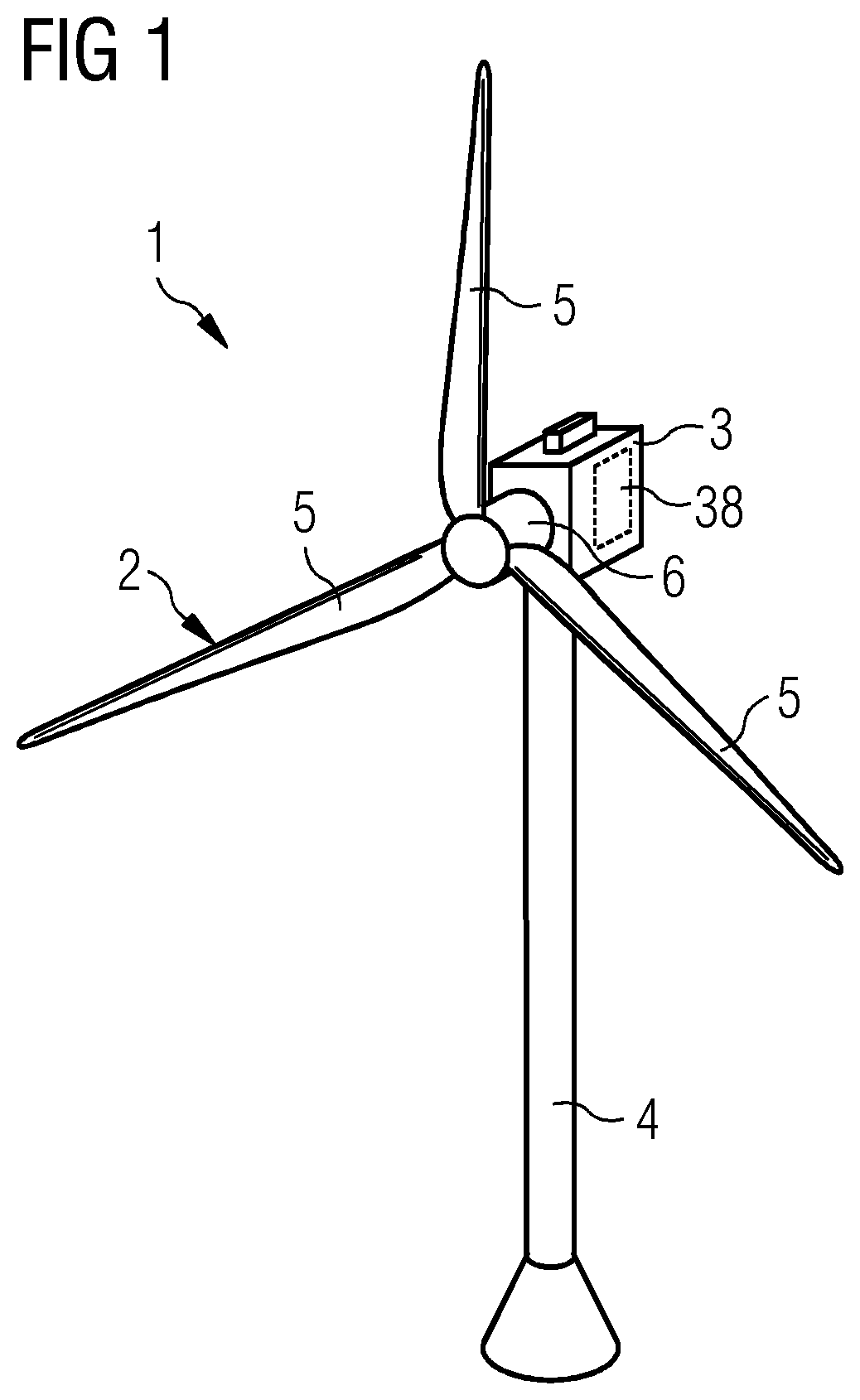
[0057]FIG. 1 shows a wind turbine 1 according to an embodiment.

[0058]The wind turbine 1 comprises a rotor 2 connected to a generator 38 arranged inside a nacelle 3. The nacelle 3 is arranged at the upper end of a tower 4 of the wind turbine 1.

[0059]The rotor 2 comprises, for example, three rotor blades 5. The rotor blades 5 are connected to a hub 6 of the wind turbine 1. Rotors 2 of this kind may have diameters ranging from, for example, 50 to 160 meters or even more. The rotor blades 5 are subjected to high wind loads. Accordingly, high loads act on a main shaft (not shown in FIG. 1) connecting the hub 6 to the generator 38.

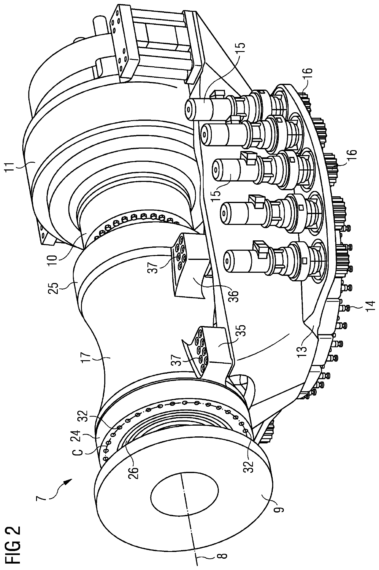
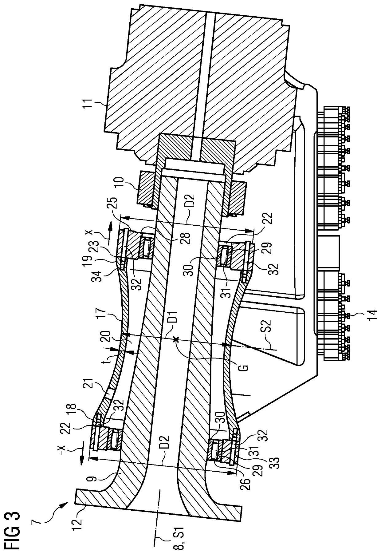
[0060]FIG. 2 shows a bearing arrangement 7 as used in the wind turbine 1 illustrated in FIG. 1. The bearing arrangement 7 is shown in a perspective view in FIG. 2. FIG. 3 illustrates a cross-section of the bearing arrangement 7. The cross-section is taken along a shaft axis 8 (see FIG. 2). The shaft axis 8 is the axis around which a main shaft 9 of the bearing a...


PUM


Abstract

A bearing arrangement for a wind turbine is provided, including a bed frame, a support structure mounted to the bed frame, a shaft, bearings supporting the shaft rotatably around a shaft axis, and bearing housings supporting one of the bearings respectively, wherein the bearing housings are mounted on opposite faces of the support structure, the faces facing in the axial direction with respect to the shaft axis. The bearing arrangement provides high bending stiffness. At the same time, the bearings in the bearings housings are easily accessible for maintenance, for example.

Description

FIELD OF TECHNOLOGY[0001]The following relates to a bearing arrangement for a wind turbine, to a wind turbine and to a method for manufacturing the bearing arrangement.BACKGROUND[0002]In wind turbines, bearing arrangements are used to support, for example, the main shaft connecting the rotor to the generator. The main shaft is subjected to substantial loads during the operation or the wind turbine. For this reason, main shafts typically have a diameter of 1 m and larger.[0003]Prior art bearing arrangements typically have one of two configurations explained hereinafter.[0004]According to a first configuration, the two bearings supporting the main shaft are housed in separate bearing housings. Each bearing housing is bolted to the bed frame inside the nacelle of the wind turbine.[0005]According to a second configuration, the two bearings supporting the main shaft are housed in a single housing. The single housing is bolted to the bed frame.[0006]Disadvantages associated with the first...

Claims


Application Information

Patent Timeline
Patent Type & Authority Applications(United States)
IPC IPC(8): F03D80/70F03D1/00F03D13/10
CPCF05B2280/1011F05B2250/17F03D1/00F05B2220/30F05B2230/60F05B2280/10F03D13/10F05B2240/50F03D80/70F16C2360/31F16C35/042Y02E10/72Y02P70/50
Inventor MOESKJAER, MARTIN
Owner SIEMENS GAMESA RENEWABLE ENERGY AS
Learn More