Sensor package substrate and sensor module having the same

a sensor module and substrate technology, applied in the direction of electrically powered generators, semiconductor electrostatic transducers, television systems, etc., can solve the problems of filter falling off from the through hole, difficult to control the attachment position of the filter, and difficult to stably fix the anti-dust filter, etc., to reduce the area of the substrate and shorten the length of the wiring

Active Publication Date: 2020-04-09
TDK CORPARATION
View PDF0 Cites 2 Cited by
  • Summary
  • Abstract
  • Description
  • Claims
  • Application Information

AI Technical Summary

Benefits of technology

[0008]According to the present invention, the step part is formed inside the through hole, whereby the anti-dust filter can be mounted at the step part. Thus, the anti-dust filter can be positioned by the step part and prevented from falling off, thereby making it possible to stably dispose the anti-dust filter inside the through hole.
[0009]In the present invention, the first section of the through hole may be opened to the one surface, and the first mounting area is positioned on the one surface side. With this configuration, it is possible to sufficiently ensure the diameter of the through hole at a portion facing the sensor chip. In this case, the second section of the through hole may be opened to the other surface. This makes the shape of the through hole comparatively simple, allowing the through hole to be formed without using a complicated process.
[0011]In the present invention, the first section of the through hole may be opened to the other surface, and the first mounting area may be positioned on the one surface side. With this configuration, it is possible to sufficiently ensure the diameter of the through hole on the other surface side, whereby, for example, sound collection characteristics can be enhanced.
[0012]In the present invention, the through hole may further include a third section having a third diameter larger than the second diameter, and the second section may be positioned between the first and second sections. Thus, it is possible to increase the opening area of the through hole on the one surface and the other surface sides while providing the step part inside the through hole. In this case, the step part inside the through hole positioned at the boundary between the second and third sections may constitute the first mounting area. This allows both the anti-dust filter and the sensor chip to be disposed inside the through hole.
[0014]The sensor package substrate according to the present invention may further include an electronic component connected to the sensor chip, and the first mounting area and the electronic component may overlap each other in a plan view. Thus, the sensor chip and the electronic component are laid out so as to overlap each other, so that when the thickness of an insulating layer interposed between the sensor chip and the electronic component is reduced, it is possible not only to shorten the length of a wiring connecting the sensor chip and the electronic component, but also to reduce the area of the substrate.
[0015]In the present invention, the sensor chip may be a sensor that detects air vibration, air pressure, air temperature or air composition. This makes it possible to detect air vibration, air pressure, air temperature or air composition through the through hole.

Problems solved by technology

However, it is not easy to stably fix an anti-dust filter such as a porous film inside the through hole and, when the anti-dust filter is fixed by simply using an adhesive, not only is it difficult to control the attachment position of the filter, but also the filter may fall off from the through hole.

Method used


Image

  • Sensor package substrate and sensor module having the same
  • Sensor package substrate and sensor module having the same
  • Sensor package substrate and sensor module having the same

Examples


first embodiment

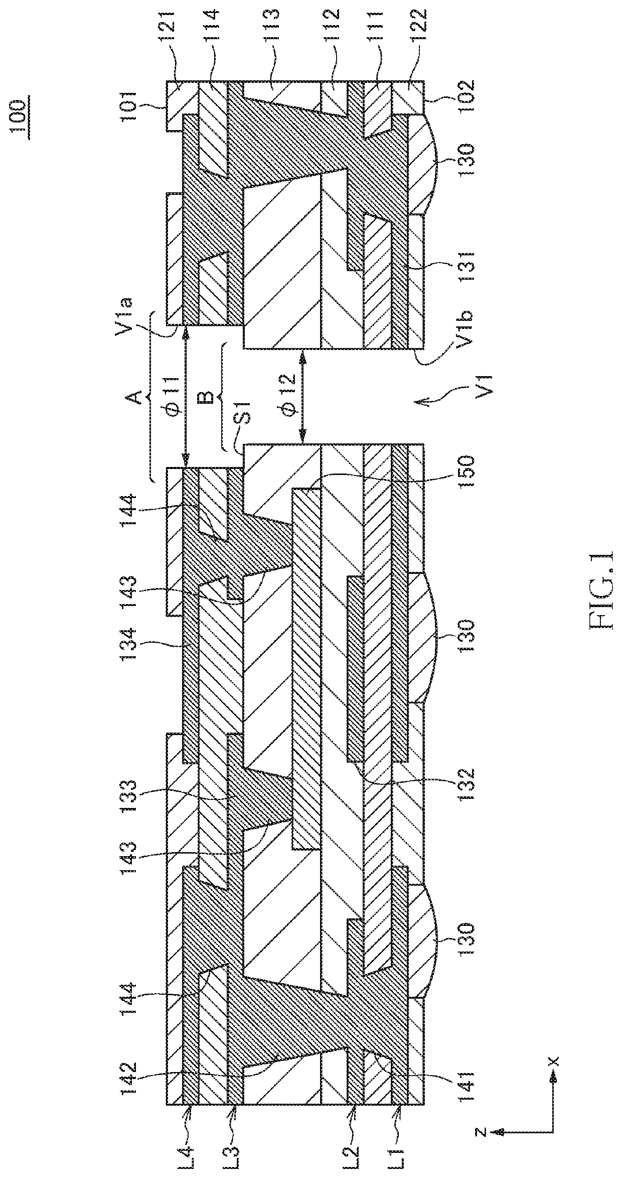
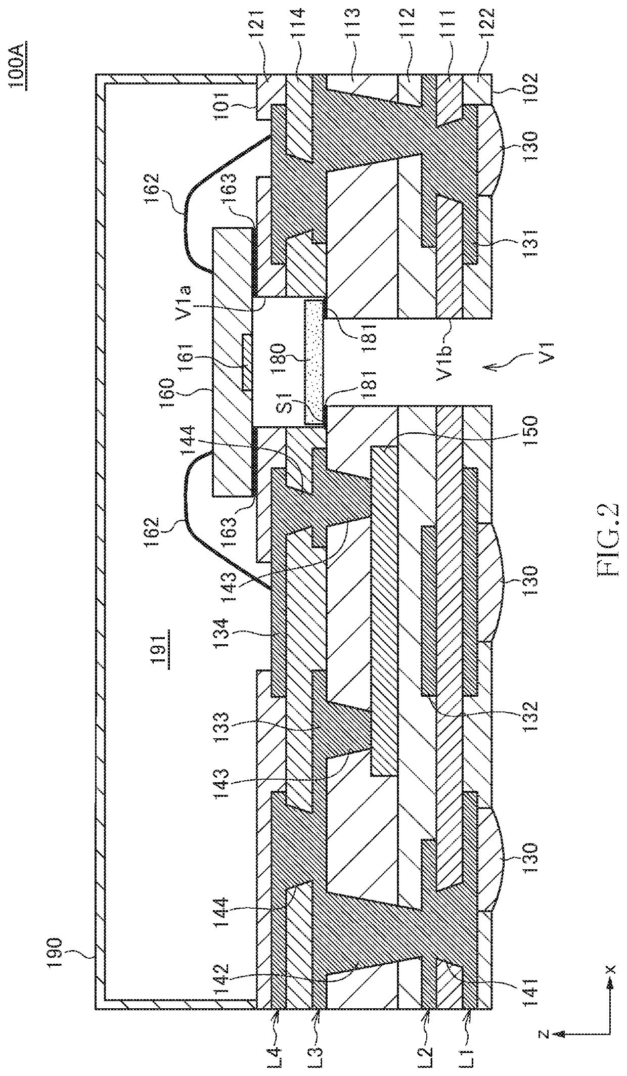
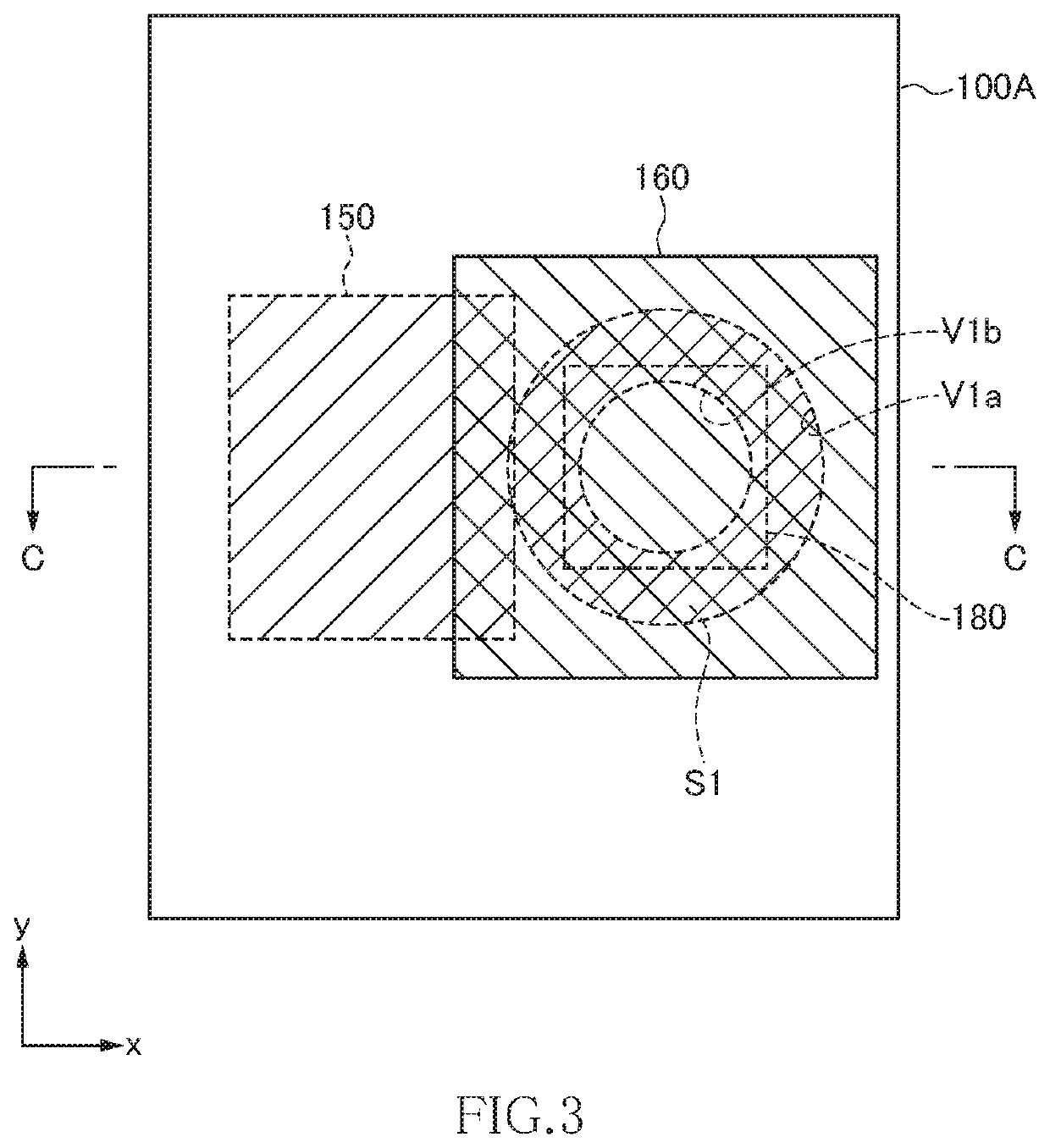
[0045]As illustrated in FIGS. 2 and 3, in the sensor module 100A a sensor chip 160 is mounted in the mounting area A of the sensor package substrate 100, and an anti-dust filter 180 is mounted in the mounting area B.

[0046]The sensor chip 160 is a sensor for detecting, e.g., air vibration, air pressure, air temperature or air composition, i.e., a microphone, a pressure sensor, a temperature sensor, a gas sensor, or the like. A detection part 161 of the sensor chip 160 is provided at a position facing the through hole V1 formed in the sensor package substrate 100. When the sensor chip 160 is, e.g., a microphone, the detection part 161 includes a vibration plate having a membrane structure. Although the position of the detection part 161 in the sensor chip 160 is not particularly limited, at least a part of the detection part 161 is exposed to the through hole V1. Thus, the detection part 161 of the sensor chip 160 is exposed to atmosphere through the through hole V1 and can thus dete...

second embodiment

[0074]FIG. 23 is a schematic cross-sectional view for explaining the structure of a sensor module 100B according to a

[0075]The sensor module 100B according to the second embodiment differs from the sensor module 100A according to the first embodiment in that the second section V1b is opened to the one surface 101 side of the sensor package substrate, and that the first section V1a is opened to the other surface 102 side. As in the first embodiment, the anti-dust filter 180 is mounted at the step part S1 positioned at the boundary between the first and second sections V1a and V1b. Other configurations are the same as those of the sensor module 100A according to the first embodiment, so the same reference numerals are given to the same elements, and overlapping description will be omitted.

[0076]In the present embodiment, the first section V1a having a larger diameter is positioned on the other surface 102 side, so that the step part S1 faces the other surface 102 side. Even with such ...

third embodiment

[0077]FIG. 24 is a schematic cross-sectional view for explaining the structure of a sensor module 100C according to a

[0078]The sensor module 100C according to the third embodiment differs from the sensor module 100B according to the second embodiment in that it has a third section V1c opened to the one surface 101 side and that the sensor chip 160 is mounted at a step part S2 positioned at the boundary between the second and third sections V1b and V1c. Other configurations are the same as those of the sensor module 100B according to the second embodiment, so the same reference numerals are given to the same elements, and overlapping description will be omitted.

[0079]As in the first and second embodiments, the anti-dust filter 180 is mounted at the step part S1 positioned at the boundary between the first and second sections V1a and V1b. A diameter ϕ13 of the third section V1c is larger than at least the diameter ϕ12 of the second section V1b, whereby the step part S2 is formed at th...


PUM

PropertyMeasurementUnit
thicknessaaaaaaaaaa
thicknessaaaaaaaaaa
thicknessaaaaaaaaaa

Abstract

Disclosed herein is a sensor package substrate that includes a first mounting area for mounting a sensor chip. The sensor package substrate has a through hole formed at a position overlapping the first mounting area in a plan view so as to penetrate the sensor package substrate from one surface to the other surface. The through hole includes a first section having a first diameter and a second section having a second diameter smaller than the first diameter. A step part inside the through hole positioned at a boundary between the first and second sections constitutes a second mounting area for mounting an anti-dust filter.

Description

BACKGROUND OF THE INVENTIONField of the Invention[0001]The present invention relates to a sensor package substrate and a sensor module having the same and, more particularly, to a sensor package substrate for mounting a sensor that detects air vibration, air pressure, air temperature, or air composition and a sensor module having the same.Description of Related Art[0002]As a sensor module having a sensor chip such as a microphone, sensor modules described in JP 2010-268412 A and JP 2010-245645 A are known. The sensor modules described in JP 2010-268412 A and JP 2010-245645 A have a substrate having a through hole and a sensor chip mounted on the substrate so as to overlap the through hole, and the sensor chip detects vibration (sound) of air entering through the through hole.[0003]The through hole formed in the substrate may serve as an intrusion path for foreign matters such as dirt and dust. To cope with this, JP 2010-268412 describes in FIG. 17 a configuration to prevent mixture ...

Claims


Application Information

Patent Timeline
Patent Type & Authority Applications(United States)
IPC IPC(8): B81C1/00B81B7/02H04R19/04H04R19/00H01L23/00
CPCH04R2201/003H01L2924/1461H01L24/48H04R19/04H01L2224/48091B81B2201/0257B81B7/02H01L2224/73265B81C1/0023H04R19/005B81B2207/012B81C2203/0109B81B2201/10H01L24/19H01L2224/48235H01L2224/48228H01L2924/15311H01L2924/15151H01L2224/73267H01L2224/04105H01L2224/32225H01L2924/16251H01L2224/92244H01L2224/24227H01L2224/16227H01L24/73H01L24/92H01L2924/00012H01L2224/48227
Inventor TSUYUTANI, KAZUTOSHISUZUKI, YOSHIHIRO
Owner TDK CORPARATION
Why Eureka
Try Eureka