Vehicle control apparatus

Active Publication Date: 2020-04-09
HONDA MOTOR CO LTD
View PDF0 Cites 0 Cited by
  • Summary
  • Abstract
  • Description
  • Claims
  • Application Information

AI Technical Summary

Benefits of technology

[0005]An aspect of the present invention is an apparatus configured to control a vehicle including an internal combustion engine and a transmission having a forward gear and a reverse gear. The apparatus includes: a torque transmission switching part configured to switch a torque transmission state to one of a forward in-gear state in which a torque output from the internal combustion engine is transmitted to an output shaft of the transmission through the forward gear, a reverse in-gear state in which the torque output from the internal combustion engine is transmitted to the output shaft of the transmission through the reverse gear, and an off-gear state in which a transmission of the torque output from the internal combustion engine to the output shaft of the transmission is blocked; a first switch instruction part configured to output a first switch instruction to switch from the forward in-gear state or the reverse in-gear state to the off-gear state; a second switch instruction part configured to output a second switch instruction to switch from the forward in-gear state to the reverse in-gear state or from the reverse in-gear state to the forward in-gear state; a torque transmission detecting part configured to detect the torque transmission state switched by the torque transmission switching part; a rotational speed changing part configured to change a rotational speed of the internal combustion engine; and an electronic control unit having a mi

Problems solved by technology

When switching between forward and reverse by changing a gear engagement from the forward gear to the reverse gear or from the reverse gear to the forward gear, a shock may be caused by torsion of the drive shaft, or unusual noise may be caused by backlash of the gear.
However, for

Method used


Image

  • Vehicle control apparatus
  • Vehicle control apparatus
  • Vehicle control apparatus

Examples


Embodiment Construction

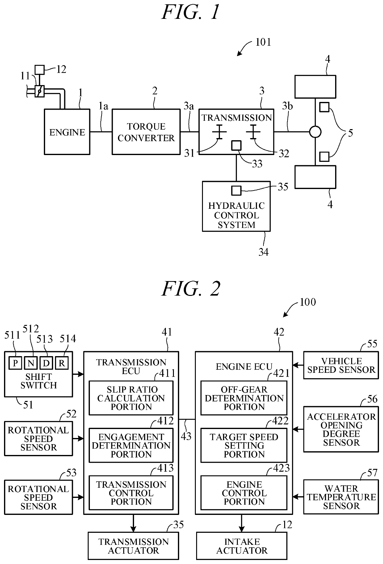
[0014]Hereinafter, an embodiment of the present invention will be described with reference to FIGS. 1 to 7. FIG. 1 is a diagram showing a schematic configuration of a travel driving system of a vehicle 101 to which a vehicle control apparatus according to an embodiment of the present invention is applied. As shown in FIG. 1, the vehicle 101 includes an engine 1, a torque converter 2, and a transmission 3.

[0015]The engine 1 is an internal-combustion engine (e.g., gasoline engine), which generates rotational power by mixing intake air supplied through an intake valve (throttle valve, etc.) 11 and fuel injected from an injector at a proper ratio and igniting the mixture using a spark plug or the like to burn the mixture. Instead of the gasoline engine, any other type of engine, such as a diesel engine may be used. The amount of intake air is controlled by an intake valve 11, and the opening degree of the intake valve 11 is changed by driving an intake actuator 12 that is driven by an e...


PUM


Abstract

A vehicle control apparatus including a torque transmission detecting part detecting a torque transmission state switched by a torque transmission switching part and a microprocessor configured to perform setting a target speed of an internal combustion engine in accordance with the torque transmission state detected by the torque transmission detecting part. The microprocessor is configured to perform the setting including increasing the target speed when a switch to the off-gear state is detected by the torque transmission detecting part after a switch instruction to an off-gear state the first is output by a first switch instruction part, while not increasing the target speed even when the switch to the off-gear state is detected by the torque transmission detecting part after a switch instruction to a reverse in-gear state or forward in-gear state is output by the second switch instruction part.

Description

CROSS-REFERENCE TO RELATED APPLICATION[0001]This application is based upon and claims the benefit of priority from Japanese Patent Application No. 2018-190067 filed on Oct. 5, 2018, the content of which is incorporated herein by reference.BACKGROUND OF THE INVENTIONField of the Invention[0002]This invention relates to a vehicle control apparatus.Description of the Related Art[0003]Conventionally, there have been known apparatuses that when the engine temperature is less than a predetermined temperature, increase the amount of intake air supplied to the engine to increase the engine speed during idling and thus prevent an engine stall. Such an apparatus is described in, for example, Japanese Unexamined Patent Publication No. H07-49048 (JPH07-049048A).[0004]When switching between forward and reverse by changing a gear engagement from the forward gear to the reverse gear or from the reverse gear to the forward gear, a shock may be caused by torsion of the drive shaft, or unusual noise ...

Claims


Application Information

Patent Timeline
IPC IPC(8): F16H61/02B60W10/10
CPCB60W2510/1005B60W10/10F16H61/0246B60W30/18045B60W10/06F02D29/02F02D31/001B60W2510/0638B60W2510/0676B60W2710/0644F02D2200/101F16H59/78F16H2059/6823F16H63/502
Inventor KAZUSA, YOSHIHIRO
Owner HONDA MOTOR CO LTD
Why Eureka
Try Eureka