Ultra-High Efficiency Single-beam and Multi-beam Inductive Output Tubes

a technology of inductive output tubes and high efficiency, applied in the field of radio frequency signal amplification systems, can solve problems such as damage to the iots

a technology of inductive output tubes and high efficiency, applied in the field of radio frequency signal amplification systems, can solve problems such as damage to the iots

US20200111636A1Active Publication Date: 2020-04-09GEORGIA TECH RES CORP

Image

  • Ultra-High Efficiency Single-beam and Multi-beam Inductive Output Tubes
  • Ultra-High Efficiency Single-beam and Multi-beam Inductive Output Tubes
  • Ultra-High Efficiency Single-beam and Multi-beam Inductive Output Tubes

Examples


Embodiment Construction

[0015]A preferred embodiment of the invention is now described in detail. Referring to the drawings, like numbers indicate like parts throughout the views. Unless otherwise specifically indicated in the disclosure that follows, the drawings are not necessarily drawn to scale. The present disclosure should in no way be limited to the exemplary implementations and techniques illustrated in the drawings and described below. As used in the description herein and throughout the claims, the following terms take the meanings explicitly associated herein, unless the context clearly dictates otherwise: the meaning of β€œa,β€β€œan,” and β€œthe” includes plural reference, the meaning of β€œin” includes β€œin” and β€œon.”

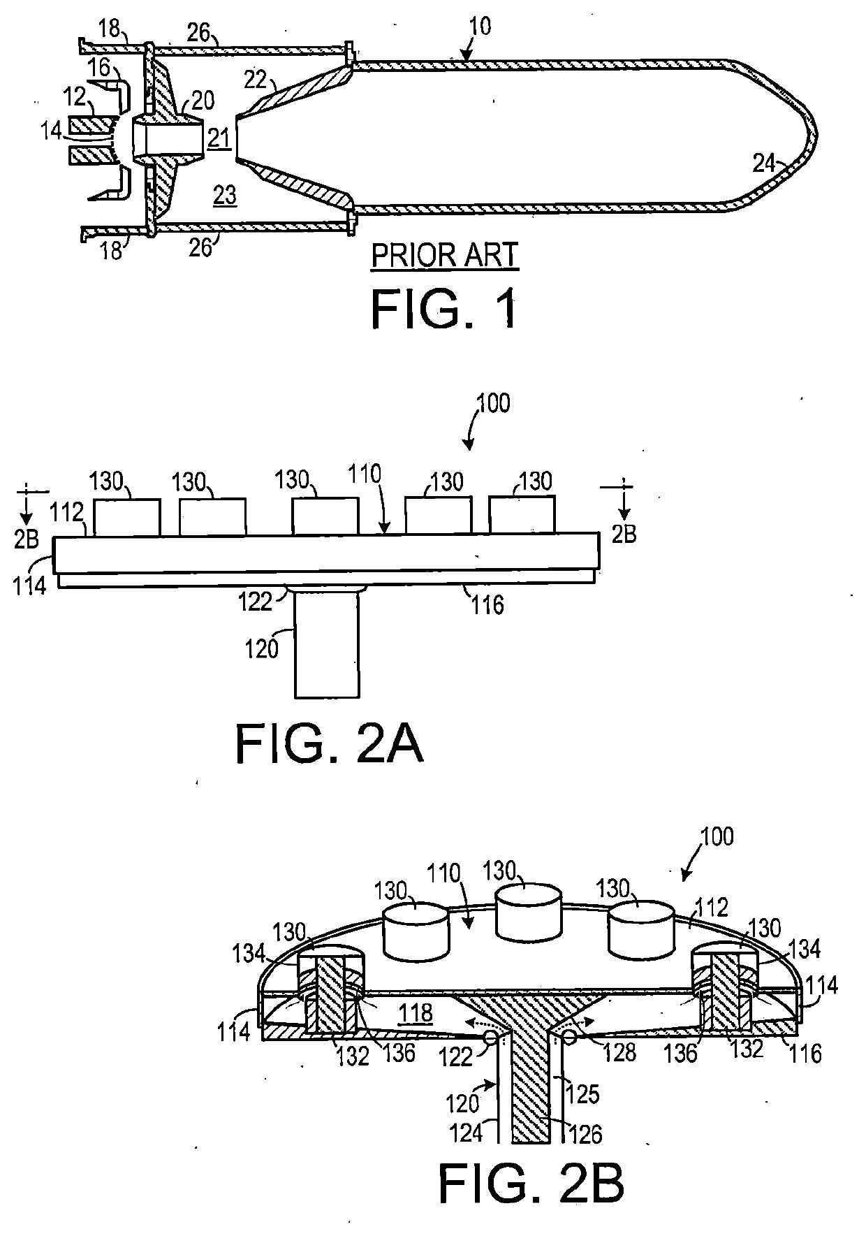
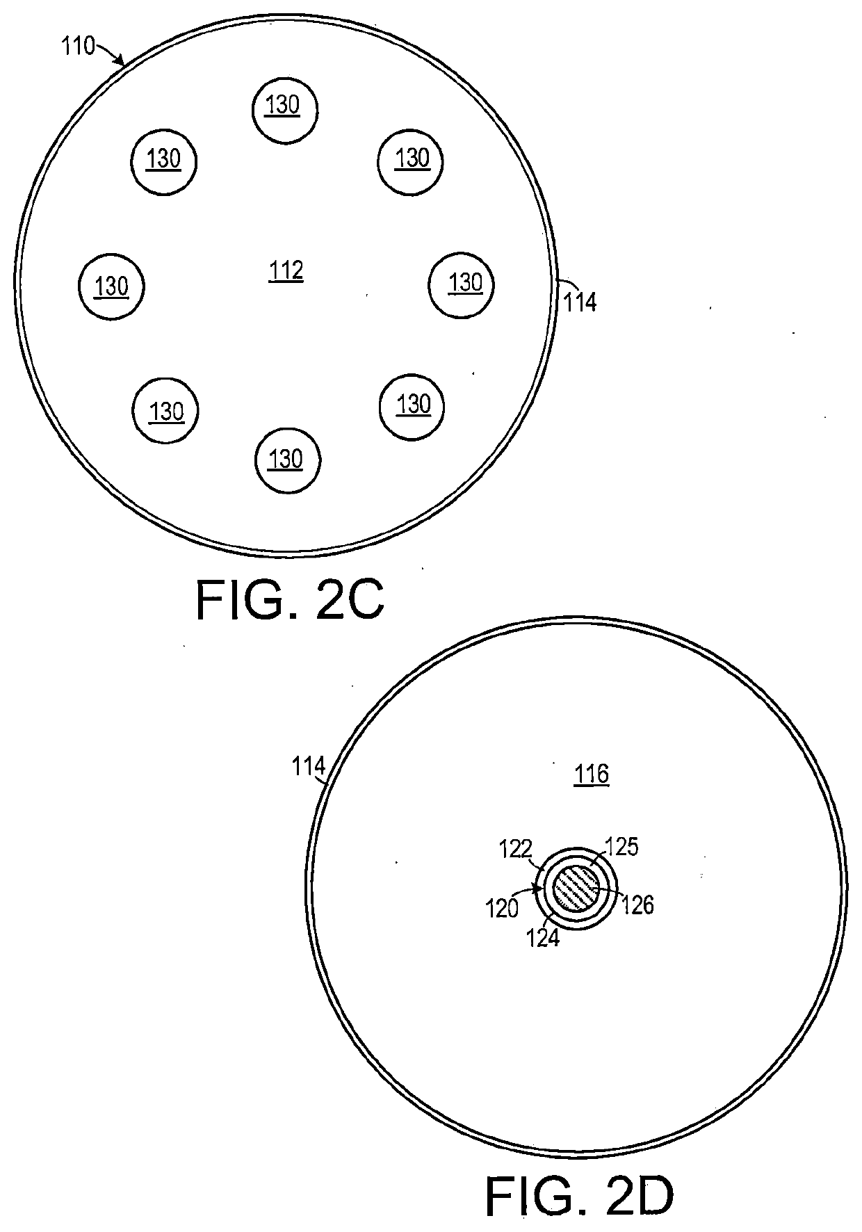
[0016]As shown in FIGS. 2A-2D, one representative embodiment of a radio frequency (RF) modulating signal splitting device 100 includes a coaxial RF input port 120 that feeds into a body frame 110 and a plurality of coaxial RF output ports 130 that are fed from the body frame 110. (It should...


PUM


Abstract

A radio frequency (RF) modulating signal splitter used by a multi-beam electron beam RF amplification system includes an RF input port and a plurality of RF output ports. A body frame distributes the RF modulating signal from the input port to the of output ports. The body frame and each one of the RF output ports have dimensions so that each one of the plurality of RF output ports is impedance matched with each other. In a method of modulating a RF input signal onto a plurality of electron beams, the RF input signal is split into a plurality of different paths directed to a plurality of output ports that are impedance matched to each other. RF energy is directed from each output port to a different input cavity of electronic beam RF amplification devices of a multi-beam electronic beam RF amplification system.

Description

CROSS-REFERENCE TO RELATED APPLICATION(S)[0001]This application claims the benefit of U.S. Provisional Patent Application Ser. No. 62 / 740,488, filed Oct. 3, 2018, the entirety of which is hereby incorporated herein by reference.BACKGROUND OF THE INVENTION1. Field of the Invention[0002]The present invention relates to radio frequency (RF) signal amplification systems and, more specifically, to a system for distributing an RF signal to a plurality of RF signal amplifying units.2. Description of the Related Art[0003]Radio frequency (RF) amplification systems for high gain applications (such as satellite communications systems and particle beam accelerators) often amplify relatively low power RF modulating signals up to an output power range from the tens of kilowatts (kW) to hundreds of kW. Such systems usually employ electron beam amplification devices, such as klystrons and inductive output tubes. While configured differently, these devices modulate an input RF signal onto a high pow...

Claims


Application Information

Patent Timeline
09 Apr 2020
Publication
US20200111636A1
IPC
H01J23/34; H01P5/16; H01J25/04
CPC
H01J23/34; H01J25/04; H01P5/16; H01P5/12
Inventors
SESSIONS, WALTER; FREUND, HENRY P.