Arc welding method and solid wire

a technology of solid wire and arc welding, which is applied in the direction of welding/cutting media/materials, welding apparatus, manufacturing tools, etc., can solve the problems of unstable arc and exhausted tip, and achieve the effect of high arc stability and excellent feeding properties

Active Publication Date: 2020-04-16
KOBE STEEL LTD
View PDF0 Cites 1 Cited by
  • Summary
  • Abstract
  • Description
  • Claims
  • Application Information

AI Technical Summary

Benefits of technology

[0022]In the present invention, it is possible to provide an arc welding method and a solid wire, excellent in feeding properties and high in arc stability during arc welding.

Problems solved by technology

In a case where welding is performed using the solid wire, wire feeding properties are excellent in short-term welding, but in long-term welding, a tip is exhausted due to fusion with the solid wire and arc tends to be unstable.

Method used


Image

  • Arc welding method and solid wire

Examples


examples

[0055]Hereinafter, the present invention is described in more detail by raising Examples, but the present invention is not limited to these Examples, and can be carried out by adding changes within the scope of the present invention, all of which are included in the technical scope of the present invention.

[0056]Various solid wires with a diameter of 1.2 mm and having a composition and average grain diameter of the copper plating film shown in Table 1 were manufactured by the method described in the embodiment, and welding was performed under the conditions shown below while controlling feed of the wire in the forward and backward direction of the wire (wire-feed controlled short-circuit arc welding method).

(1) Steel Sheet

[0057]A steel sheet of 200 mm in length×60 mm in width×3.2 mm in thickness was used. A steel type of the steel sheet was SPHC590.

(2) Welding Position

[0058]Lap fillet welding was performed.

(3) Shielding Gas

[0059]Ar+20 volume % of CO2 was used as the shielding gas.

(4...


PUM

PropertyMeasurementUnit
grain diameteraaaaaaaaaa

Abstract

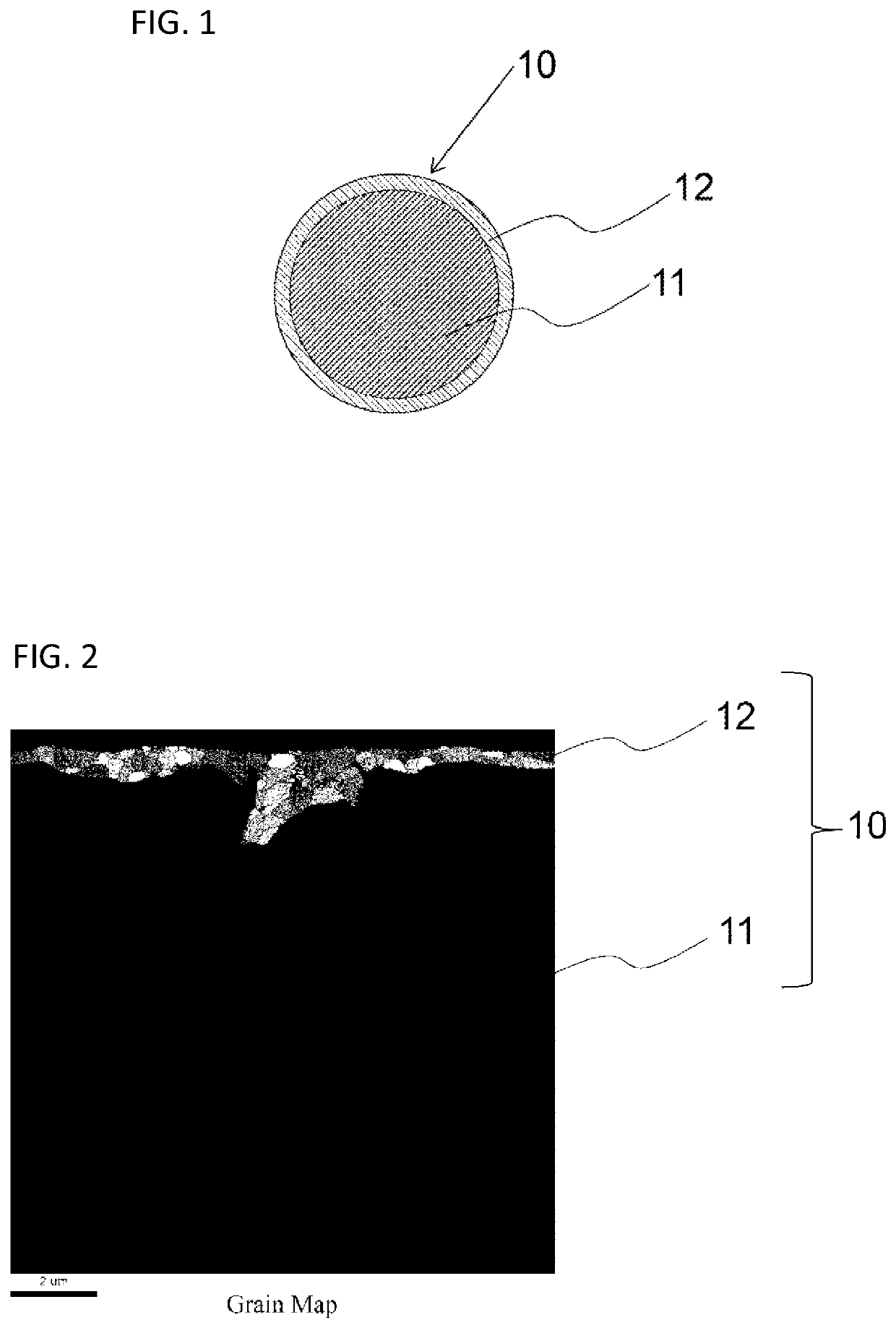
An arc welding method includes performing welding by using a gas and a solid wire. The gas contains Ar. The solid wire includes a steel core wire and a copper plating film formed on a surface of the steel core wire, and the copper plating film has an average grain diameter of 600 nm or less.

Description

TECHNICAL FIELD[0001]The present embodiment relates to an arc welding method and a solid wire.BACKGROUND ART[0002]A solid wire is widely used in gas shielded arc welding for a thin plate of automobiles or the like. In a case where welding is performed using the solid wire, wire feeding properties are excellent in short-term welding, but in long-term welding, a tip is exhausted due to fusion with the solid wire and arc tends to be unstable.[0003]Here, when a copper plating film is formed on a surface of the solid wire, it is generally common that tip abrasion is reduced and an arc is stable during welding. For example, Patent Literature 1 discloses a solid wire with a copper plating film having a thickness of 0.3 μm to 1.1 μm formed on a surface thereof.CITATION LISTPatent Literature[0004]Patent Literature 1: JP 2008-194716 A[0005]Patent Literature 2: Japanese Patent No. 6043969SUMMARY OF INVENTIONTechnical Problem[0006]There is a common welding method (wire-feed controlled short-cir...

Claims


Application Information

Patent Timeline
Patent Type & Authority Applications(United States)
IPC IPC(8): B23K9/173B23K35/02B23K35/30
CPCB23K9/173B23K35/0261B23K35/3026B23K9/12B23K35/3053B23K35/3073C25D7/0607C25D3/58C25D5/36C25D5/48C25D5/50C25D5/617
Inventor KINASHI, HIKARUYOKOTA, YASUYUKISATO, KOJI
Owner KOBE STEEL LTD
Why Eureka
Try Eureka