Friction plate and clutch assembly including the same

a technology of friction plate and clutch assembly, applied in the field of friction plate, can solve the problems of increasing drag torque, reducing the performance of the clutch assembly, and affecting so as to reduce the drag torque, increase the performance of the clutch assembly, and reduce the effect of wet friction system

Active Publication Date: 2020-04-16
BORGWARNER INC
View PDF0 Cites 0 Cited by
  • Summary
  • Abstract
  • Description
  • Claims
  • Application Information

AI Technical Summary

Benefits of technology

[0007]Accordingly, the core plate including the fluid directing portion having the second thickness greater than the first thickness limits drag torque in the clutch assembly, which ultimately increases performance of the clutch assembly, and increases fuel economy.

Problems solved by technology

However, clutch assemblies including conventional friction plates often experience drag torque when the plurality of friction plates are rotating in the disengaged position, which is caused by the friction plates rotating through the lubricant.
Increased drag torque reduces performance of the clutch assembly and, in turn, the wet friction system, and reduces fuel economy of the motor vehicle's power generator.

Method used


Image

  • Friction plate and clutch assembly including the same
  • Friction plate and clutch assembly including the same
  • Friction plate and clutch assembly including the same

Examples


Embodiment Construction

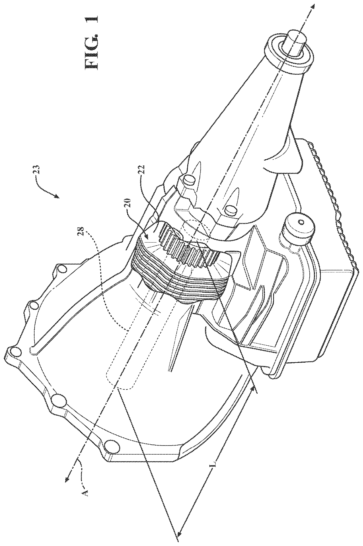
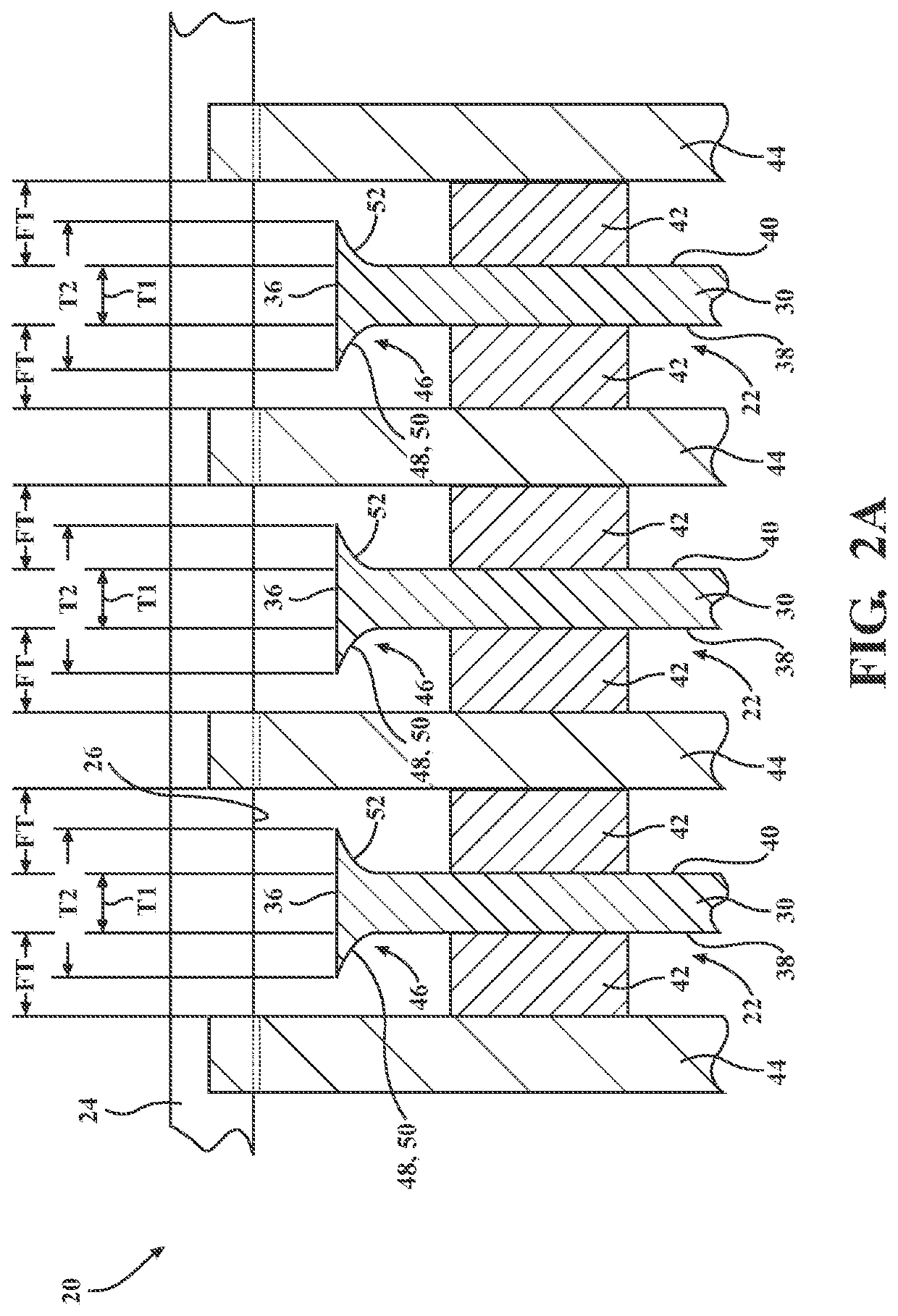
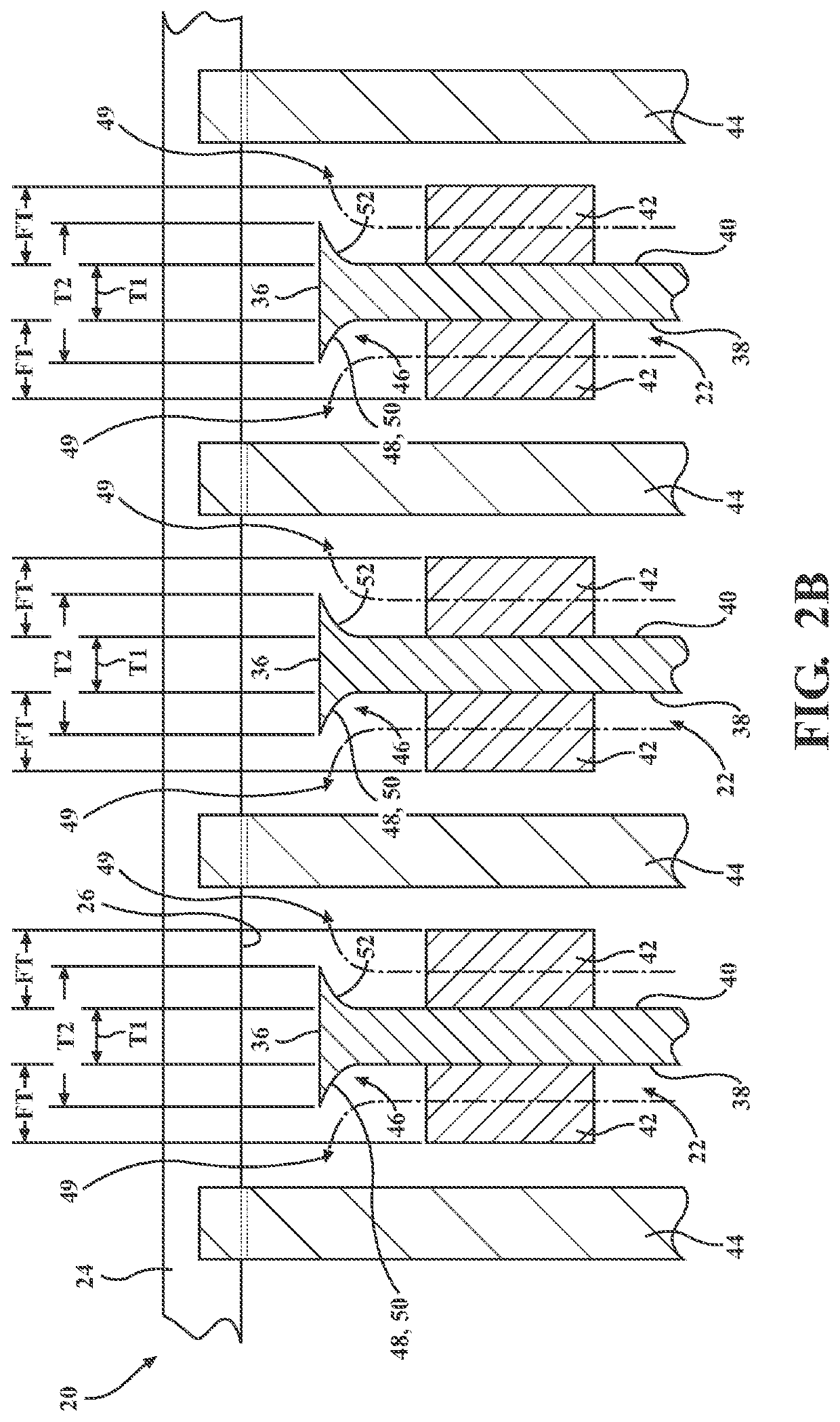
[0020]With reference to the Figures, wherein like numerals indicate like parts throughout the several views, a clutch assembly 20 including a friction plate 22 is generally shown in FIG. 1. The friction plate 22 is used in the clutch assembly 20 for use in a wet friction system 23. Examples of wet friction systems include transmissions, particularly automatic transmissions, continuously variable transmissions, automated manual transmissions, dual clutch transmissions, wet friction brake systems, and the like. With reference to FIGS. 2A and 2B, the clutch assembly 20 includes a housing 24 defining a clutch interior 26. The friction plate 22 is disposed in the clutch interior 26. With reference to FIG. 1, the clutch assembly 20 also includes a shaft 28 having a length L and an axis A extending along the length L.

[0021]With reference to FIG. 2A through 6B, the friction plate 22 includes a core plate 30 defining a bore 32 extending along the axis A. The bore 32 receives the shaft 28 suc...


PUM


Abstract

A friction plate includes a core plate defining a bore. The core plate includes an interior core surface defining the bore, an exterior core surface radially spaced from the interior core surface, a first clutch face extending between the interior core surface and the exterior core surface and facing a first direction, and a second clutch face extending between the interior core surface and the exterior core surface and facing a second direction opposite the first direction. The friction plate also includes a friction material disposed on at least one of the first and second clutch faces. The core plate also includes a fluid directing portion. A first plate thickness is defined between the first and second clutch faces. A second plate thickness is defined at the fluid directing portion. The second thickness is greater than the first thickness.

Description

BACKGROUND OF THE INVENTION1. Field of the Invention[0001]The present invention generally relates to a friction plate and, more specifically, to a friction plate for use in a clutch assembly of a wet friction system.2. Description of the Related Art[0002]Several components of a motor vehicle powertrain may employ a wet friction system to facilitate the transfer of power from the motor vehicle's power generator (e.g., an internal combustion engine, electric motor, fuel cell, etc.) to drive wheels of the motor vehicle. A transmission, located downstream from the power generator that enables vehicle launch, gear shifting, and other torque transfer events, is one such component that may employ a wet friction system. Some form of a clutch assembly may be found throughout many different types of transmissions currently available for motor vehicle operation. A wet clutch may be utilized in a torque converter for an automatic transmission, in a multi-plate wet clutch pack for an automatic t...

Claims


Application Information

Patent Timeline
Patent Type & Authority Applications(United States)
IPC IPC(8): F16D13/64F16D13/74F16D13/52F16D13/70
CPCF16D13/52F16D2300/14F16D13/74F16D2300/10F16D13/648F16D13/70
Inventor SIEGEL, BENJAMIN A.ELSESSER, PAUL H.PRIDGEN, JR., RICHARD W.VIERK, DAVID T.
Owner BORGWARNER INC
Why Eureka
Try Eureka