
Energy-saving hydraulic winch

A hydraulic winch, energy-saving technology, applied in hoisting devices, clockwork mechanisms, etc., can solve problems such as low mechanical efficiency, affecting clutch performance, insufficient radial positioning, etc., to reduce maintenance and repair costs, and stabilize clutch performance Reliable and guaranteed performance stability

Active Publication Date: 2013-06-12
INI HYDRAULIC
View PDF1 Cites 0 Cited by
  • Summary
  • Abstract
  • Description
  • Claims
  • Application Information

AI Technical Summary

Problems solved by technology

[0002] In order to solve the problems of the complex and difficult processing of the hydraulic winch with clutch, the unbalanced force of the power shaft in the hydraulic winch, the axial thrust on the frame and the inability to realize the modularization of the clutch components, the inventor proposed a method called " The technology of "Hydraulic Winch with Clutch at the Final Stage of Transmission" (Authorized Notification No. CN 101190770 B) shows a hydraulic winch with clutch at the final stage of transmission with balanced force on the power shaft, simple structure, and convenient processing and disassembly. It is composed of hydraulic motor, hydraulic brake, planetary gear reducer, hydraulic clutch, reel and hydraulic control circuit to control its work. The hydraulic clutch set in the reel is at the end of the system transmission chain, and the planetary gear reducer is set in the reel. Inside the barrel, the right output end of the last stage planet carrier is the spline shaft connected to the multi-plate friction clutch, the right end of the spline shaft is the piston of the clutch control cylinder, the planet carrier of the planetary gear reducer and the spline of the clutch Shaft and piston are integrated structure
This authorized patent effectively solves the problems of the existing hydraulic winch, such as complex connection structure, difficult processing and assembly, unbalanced force on the power shaft, easy wear of the joint of the frame subjected to axial force, low mechanical efficiency and short service life. In the long-term production practice and use process, it is found that there are still some deficiencies: 1. The relative friction between the clutch friction plates, the gear transmission in the planetary gear reducer, and the braking action of the brake will all produce a lot of heat , because the clutch, reducer, and brake are all installed in the reel, the space is closed, and the heat is difficult to spread to the outside, resulting in a serious temperature rise in the reel, especially in a hot environment, the temperature inside the reel is higher, and the excessive temperature will cause 2. The friction of the clutch friction plate will cause debris, which will be deposited on the surface of the reel and friction plate, which can seriously affect the performance of the clutch; 3. The spline shaft of the clutch It is spline connected with the final stage planet carrier, and the other end is sleeved on the oil delivery shaft. This fixed structure makes the spline shaft in a suspended state, which has the problem of insufficient radial positioning, and is prone to beating and noise during operation. It will lead to insufficient parallelism between the fixed friction plate and the dynamic friction plate on the spline shaft, thereby affecting the performance of the clutch; 4. The outer cylinder of the clutch is fixed on the inner wall in the middle of the reel, and the reel is fixed on the support shaft through bearings structure, so that the vibration of the clutch is directly transmitted to the reel, making the operation of the reel unstable, and the structure is not compact enough, and it is not easy to assemble and disassemble; 5. The structure of the oil delivery shaft between the support shaft and the spline shaft is complicated Inconvenient to install
[0003] In addition, the winch has the function of free release, and the free release function has two working states, one is free release of the empty hook without heavy objects, and the other is free release of heavy hooks with heavy objects; the existing process of free release of heavy hooks The speed control and braking in the winch are realized by using a special brake set outside the reel and the casing is installed on the frame. This structure not only increases the volume, length and weight of the winch, but also increases the size In the situation, the planet carrier and the gear in the reel are in a rotating state, thereby increasing the resistance. For this reason, this kind of winch cannot realize the function of free lowering of the empty hook, and the structure is complicated and the production cost is expensive; Integrated hydraulic winch with controllable free-flowing speed" (authorized announcement number CN 2876042Y) technology, by setting a band brake outside the reel, can control the speed of free-falling, but it has the disadvantages of complex structure and occupying the space outside the reel

Method used


Image

  • Energy-saving hydraulic winch
  • Energy-saving hydraulic winch
  • Energy-saving hydraulic winch

Examples


Embodiment

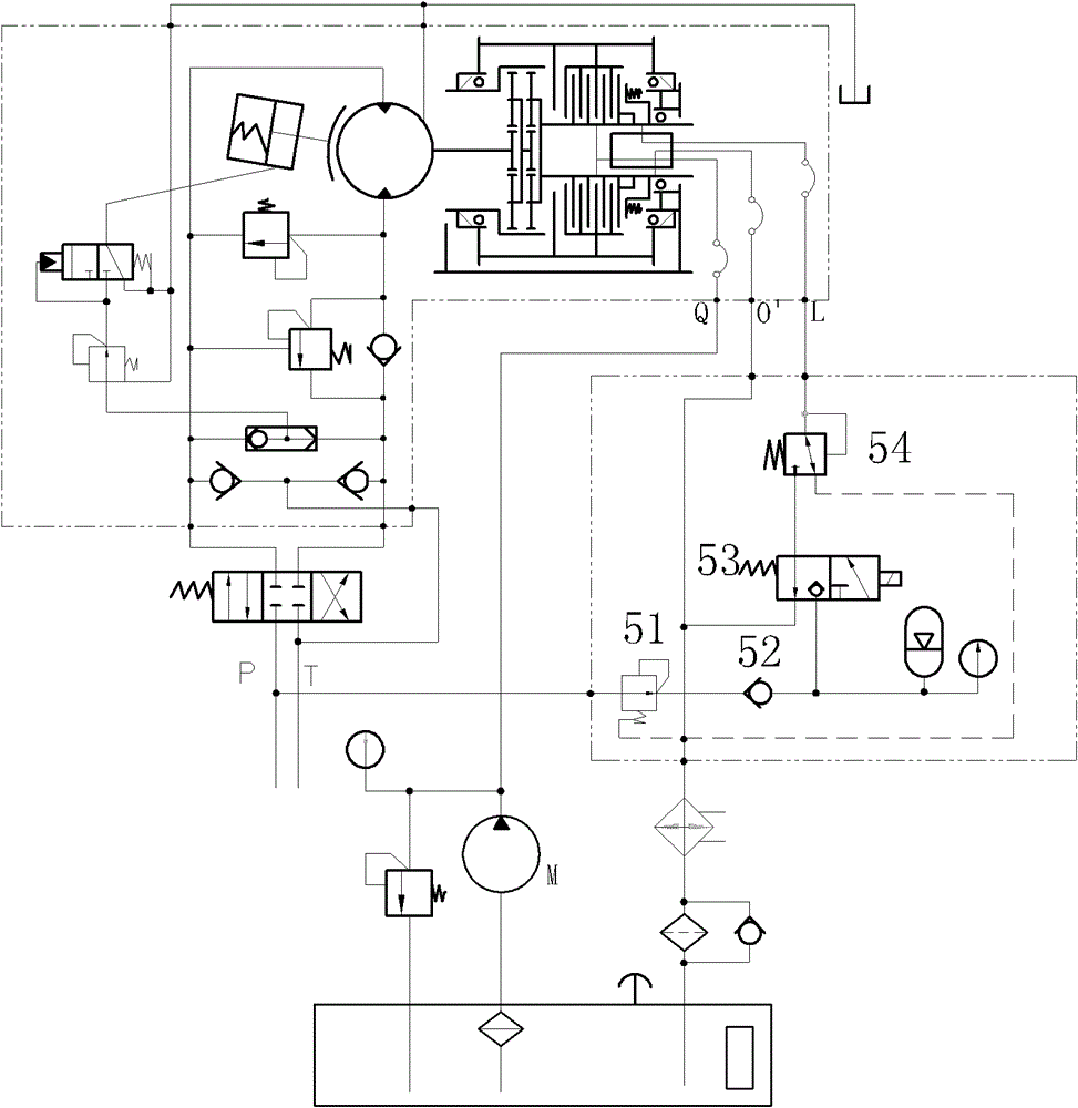
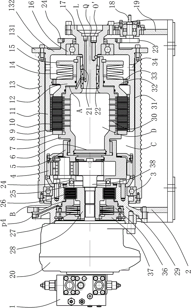
[0030] Embodiment: The energy-saving hydraulic winch of the present invention, as attached figure 1 , attached image 3 As shown, it includes a frame, a reel 13, a hydraulic motor 20, a hydraulic control block 1, a cooling system, a hydraulic control system, and a hydraulic brake, a planetary gear reducer 4 and a hydraulic clutch located in the reel 13; the hydraulic clutch includes The outer cylinder 11, the fixed friction plate 10, the moving friction plate 9 and the clutch oil cylinder that drives the two friction plates to be clutched. The clutch oil cylinder includes a cylinder body 12, a piston 7 and a disc spring 14; There is a clutch oil chamber A between the 7; the disc spring 14 is fixed on the piston 7 through the block 15 . The fixed friction plates 10 and the movable friction plates 9 are alternately arranged on the outer cylinder 11 and the piston 7 .

[0031] The cooling system includes a cooling chamber and a liquid supply system that supplies circulating coo...

Embodiment 2

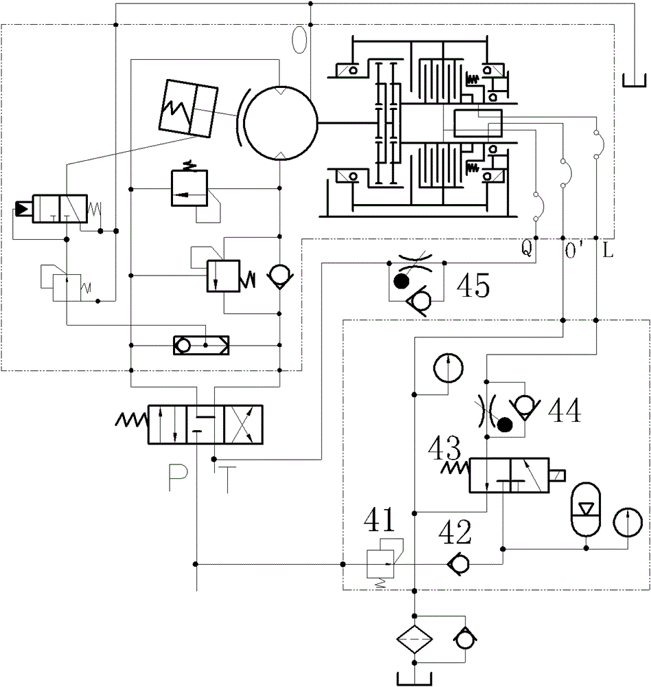
[0047] Embodiment 2: as attached figure 2 As shown, the liquid inlet circuit of the liquid supply system is directly connected to the oil return passage of the main hydraulic system, and the back pressure of the oil return oil passage is used to supply liquid to the cooling chamber, and the flow is controlled through the throttle valve 45; the oil return passage of the oil return passage The back pressure is 0.2-0.8 MPa. The back pressure of the oil return passage is not less than 0.2MPa. All the other are with embodiment 1.


PUM


Abstract

The invention relates to an energy-saving hydraulic winch. The energy-saving hydraulic winch comprises a hydraulic brake, a planetary reducer, a hydraulic clutch, a hydraulic control system and a cooling system, wherein the cooling cavity of the cooling system comprises an inner cavity which is arranged on the middle part of a piston of a clutch oil cylinder and an outer cavity which enwraps a clutch friction plate; a plurality of liquid guiding holes for communicating the inner cavity and the outer cavity are formed on the circumference of the piston; a liquid supplying system, the inner cavity, the liquid guiding holes and the outer cavity form a circulating system; refrigerating medium flows in the circulating system to cool the clutch friction plate immersed in the outer cavity, take away scraps and other impurities generated by the clutch friction plate and cool the reducer and the brake; and a control loop for controlling a heavy hook to be put down freely is arranged on the control loop of the hydraulic clutch, and the speed control and the braking are performed by employing the clutching friction when a heavy object is put down freely, along with stable control and reliable braking, so that the braking moment of the reducer is greatly reduced, the service life of an inner gear of the reducer is prolonged, and the maintenance cost and the repairing cost are reduced.

Description

technical field [0001] The invention relates to a winch for winding steel wire ropes, in particular to an energy-saving hydraulic winch. Background technique [0002] In order to solve the problems of the complex and difficult processing of the hydraulic winch with clutch, the unbalanced force of the power shaft in the hydraulic winch, the axial thrust on the frame and the inability to realize the modularization of the clutch components, the inventor proposed a method called " The technology of "Hydraulic Winch with Clutch at the Final Stage of Transmission" (Authorized Notification No. CN 101190770 B) shows a hydraulic winch with clutch at the final stage of transmission with balanced force on the power shaft, simple structure, and convenient processing and disassembly. It is composed of hydraulic motor, hydraulic brake, planetary gear reducer, hydraulic clutch, reel and hydraulic control circuit to control its work. The hydraulic clutch set in the reel is at the end of the...

Claims


Application Information

Patent Timeline
Patent Type & Authority Patents(China)
IPC IPC(8): B66D1/08B66D1/28B66D1/44B66D1/22B66D5/26
Inventor 胡世璇
Owner INI HYDRAULIC
Learn More