
Systems and methods for measurement of gas concentration difference between inhalation and exhalation

a gas concentration difference and gas concentration technology, applied in the field of gas concentration measurement, can solve the problems of difficult to obtain accurate gas concentration measurement of biological samples, difference between inspiration (0%) and expiration, and increase the difficulty of gas concentration measuremen

Pending Publication Date: 2020-04-23
THE FEINSTEIN INST FOR MEDICAL RES +1
View PDF2 Cites 5 Cited by
  • Summary
  • Abstract
  • Description
  • Claims
  • Application Information

AI Technical Summary

Benefits of technology

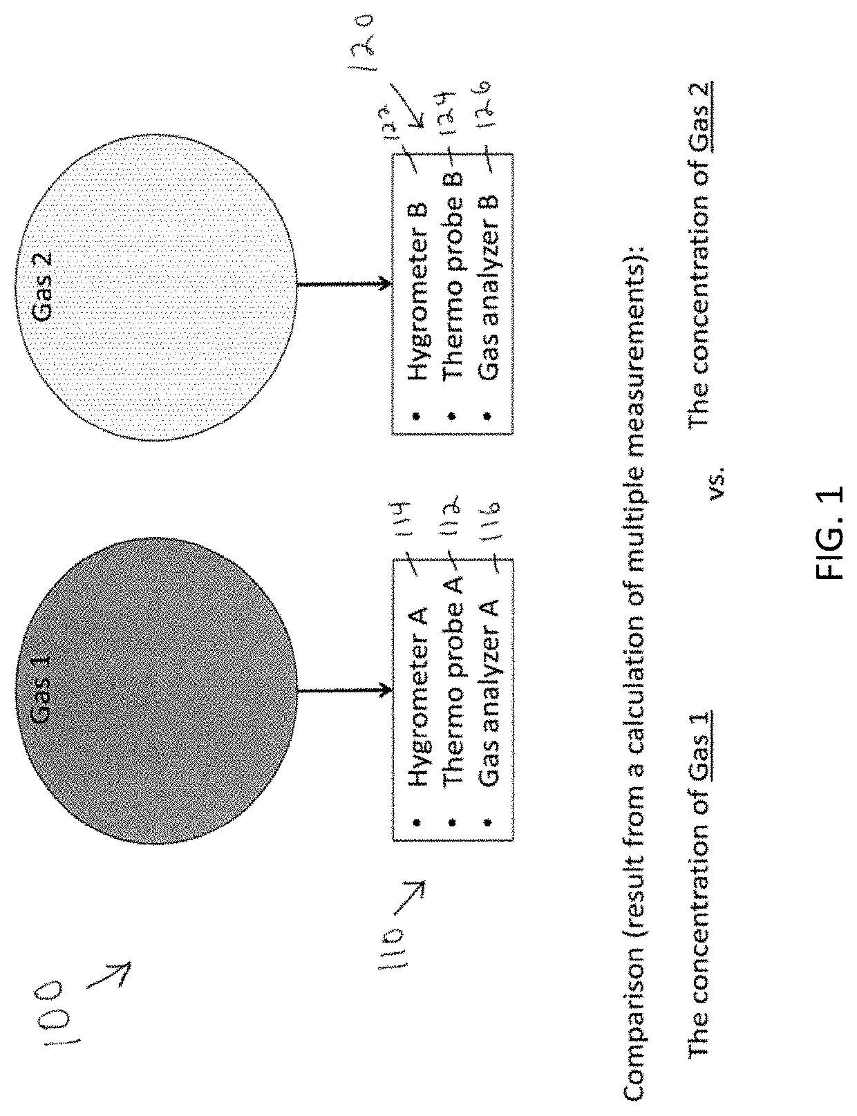
The present invention is a system and method aimed at accurately measuring the difference in gas concentration between a patient's inhalation and exhalation. The technical effect is the ability to accurately measure gas concentrations in a patient's breath.

Problems solved by technology

However, obtaining an accurate measurement of gas concentration in biological samples is very challenging.
Condition of the gas, such as temperature, pressure, humidity, and density, can be a cause of measurement errors.
These errors might be compounded when attempting to measure the concentration difference between two different gas flows because the conditions of the gases might differ from one another.
This humidity difference between inspiration (0%) and expiration (30-100%) is a significant obstacle in achieving an accurate measurement of the gas concentration differences between inspiration and expiration in a patient who is mechanically ventilated.
However, most conventional measurement devices fail to provide an adequate real-time measurement of O2 consumption, which is mainly due to inaccurate measurement of the concentration difference between inhalation and exhalation.

Method used


Image

  • Systems and methods for measurement of gas concentration difference between inhalation and exhalation
  • Systems and methods for measurement of gas concentration difference between inhalation and exhalation
  • Systems and methods for measurement of gas concentration difference between inhalation and exhalation

Examples


example

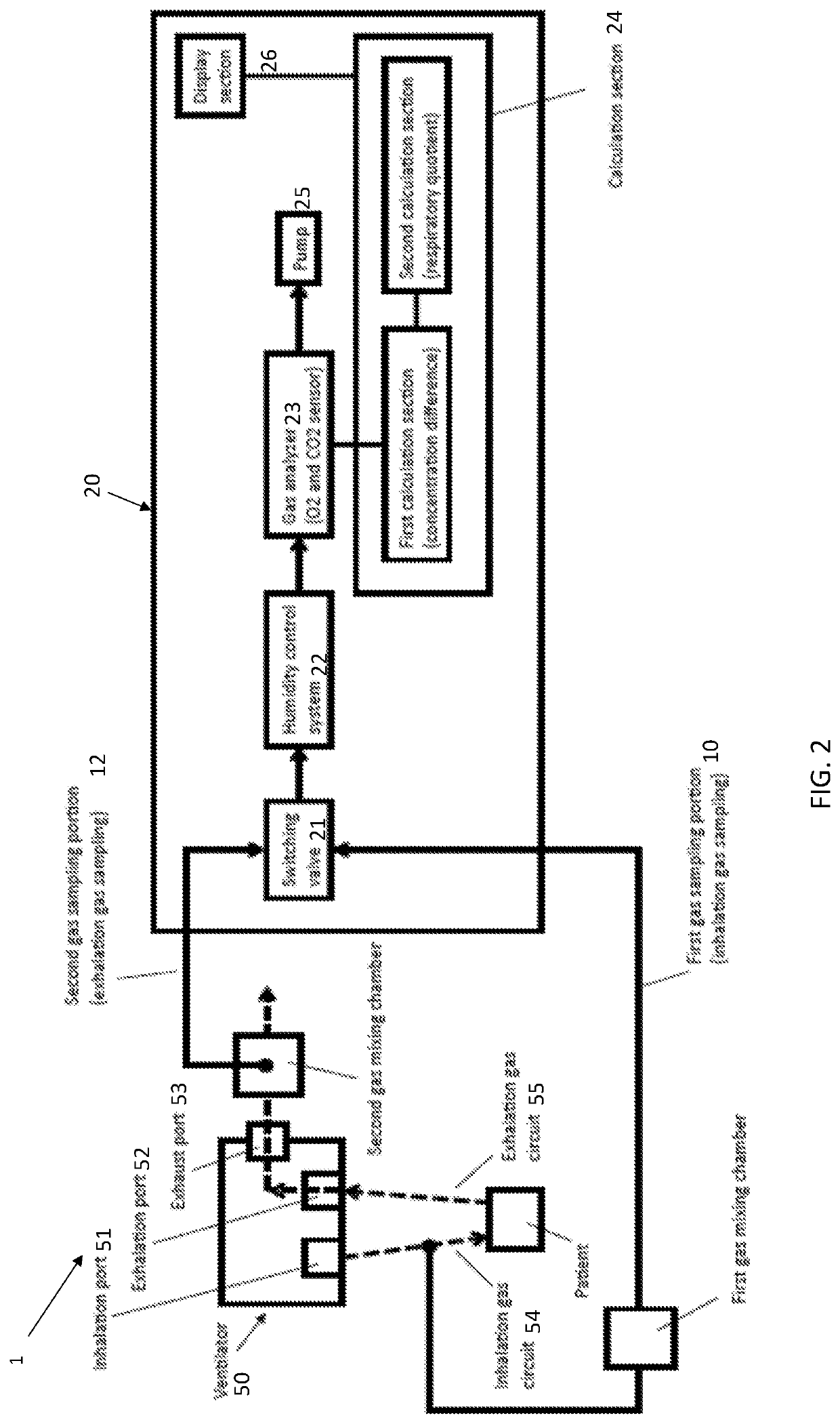
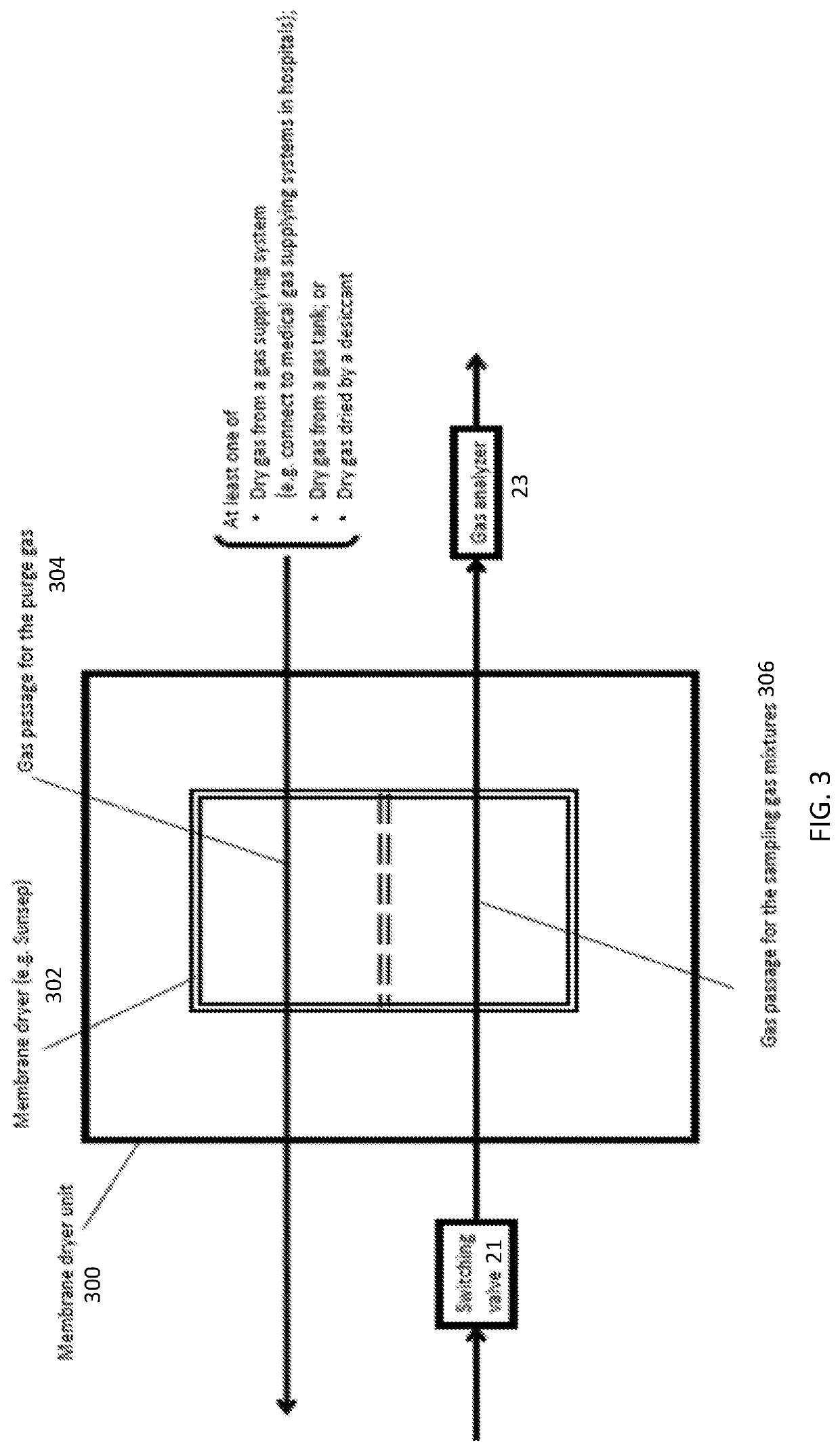
[0050]The same test lung, mechanical ventilator and gas analyzer from the Comparative Example were used to measure CO2 and O2 concentrations in inhaled and exhaled air, but instead of using the Douglas Bag method, the test was performed using a system including two chambers (one for each of inhaled gas and exhaled gas), a humidity control system for equilibrating humidity levels within each chamber, a single gas analyzer and a switching valve to control gas flow from the chambers to the gas analyzer. This was a conceptual proof experiment of a real-time measurement with humidity control. Two separate 250 mL glass bins were prepared. These glass bins were frozen inside a dry ice container. The exhaled gas and the inhaled gas were sampled directly from the mechanical ventilation circuit through a sampling port added into the ventilation circuit. The exhaled (exhaust) gas was passed through one of the bins and the inhaled gas was passed through another bin. The gas analyzer was connect...


PUM


Abstract

A system including a first sampling portion configured to sample inhalation gas made up of a first gaseous mixture, a second sampling portion configured to sample exhalation gas made up of a second gaseous mixture, a gas analyzer configured to measure gas concentrations, a switching valve that controls flow of the sampled inhalation gas and the sampled exhalation gas to the gas analyzer so as to alternately measure concentration of gaseous components within the first and second gaseous mixtures, a humidity control system that maintains humidity within the first and second gaseous mixtures to a predetermined humidity level, and a calculation section configured to calculate concentration differences of the gaseous components between the first and second gaseous mixtures.

Description

RELATED APPLICATION[0001]This application claims priority to and the benefit of U.S. Provisional Patent Application No. 62 / 746,641, filed Oct. 17, 2018, the contents of which are incorporated herein by reference in their entirety.TECHNICAL FIELD[0002]The present invention is directed to measurement of gas concentrations, and in particular is directed to systems and methods for measuring and comparing concentration of gaseous components within different gaseous mixtures.BACKGROUND[0003]A clinician might measure the concentration of a specific type of gas within different gaseous mixtures and use this information to determine how the concentrations vary between the gas mixtures. This measured comparison of gas concentration might be useful for patient diagnosis or a clinical study. However, obtaining an accurate measurement of gas concentration in biological samples is very challenging. Condition of the gas, such as temperature, pressure, humidity, and density, can be a cause of measu...

Claims


Application Information

Patent Timeline
IPC IPC(8): A61B5/097A61M16/08A61B5/08A61B5/093A61B5/083A61M16/20A61B5/087
CPCA61B5/0833A61B5/0836A61B5/087A61M16/208A61B5/093A61B5/082A61B5/0878A61B5/097A61M16/085
Inventor BECKER, LANCELAMPE, JOSHSHINOZAKI, KOICHIROSAEKI, KOTAWEISNER, STEVEYAMAMORI, SHINJI
Owner THE FEINSTEIN INST FOR MEDICAL RES
Learn More