
Light-emitting device for lamp

Active Publication Date: 2020-04-23
DONGGUAN CITY MINLEON ELECTRONICS CO LTD
View PDF1 Cites 0 Cited by
  • Summary
  • Abstract
  • Description
  • Claims
  • Application Information

AI Technical Summary

Benefits of technology

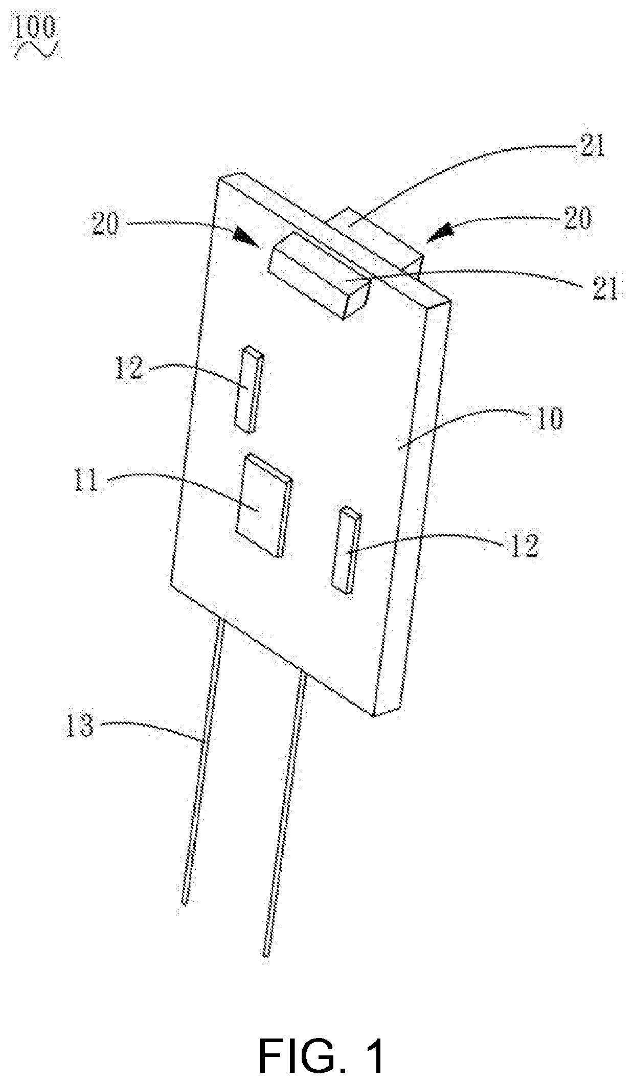
The light-emitting device described in this patent text has a pad on the circuit board that matches the design of a patch LED lamp. The patch LED lamp is then directly mounted on the pad with a 90-degree angle between the LED surface and the pad. This design eliminates the need for two circuit boards, saving time and money. It also increases production efficiency.

Problems solved by technology

However, such manufacturing method of the LED lamp increases labor costs and reduces production efficiency.

Method used


Image

  • Light-emitting device for lamp
  • Light-emitting device for lamp
  • Light-emitting device for lamp

Examples


Embodiment Construction

[0018]In order to facilitate the understanding of the present disclosure, the present disclosure will be more fully described below. However, the disclosure may be implemented in many different forms and is not limited to the embodiments described herein. Rather, these embodiments are provided to provide a more comprehensive understanding of the content of the disclosure.

[0019]It should be noted that when an element is referred to as being “fixed” to another element, it may be directly disposed on another element or disposed therein. When an element is considered to be “connected” to another element, it may be directly connected to another element or disposed therein.

[0020]Unless otherwise defined, all the technical and scientific terms used herein have the same meaning as commonly understood by persons of ordinary skill in the art of the disclosure. The terminologies used in the description of the present disclosure are for the purpose of describing particular embodiments and are n...


PUM


Abstract

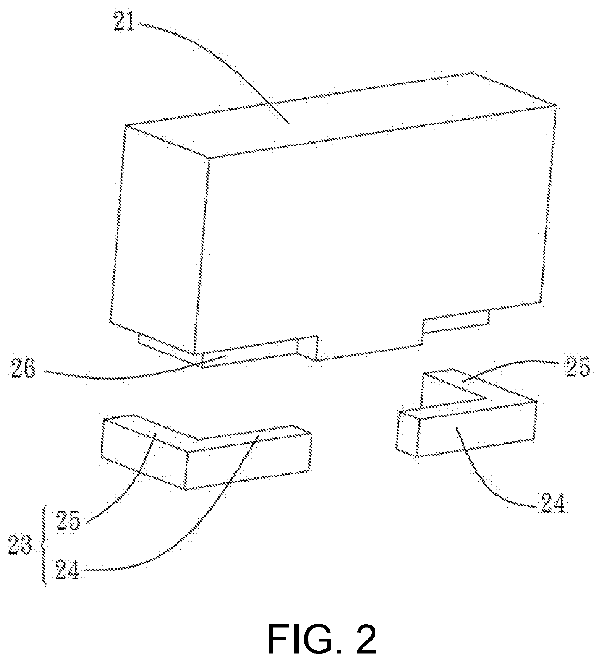
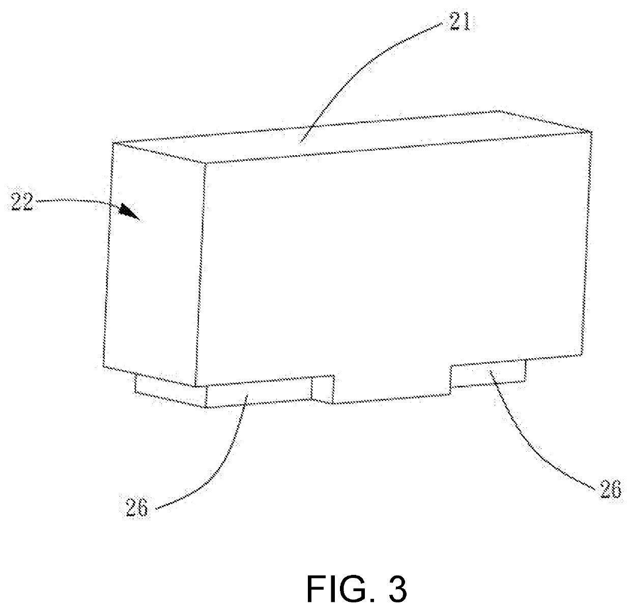
The disclosure is related to a light-emitting device for lamp, including a circuit board and a patch LED lamp. The circuit board is provided with an LED driving chip and a plurality of resistor elements. The circuit board is provided with a pad corresponding to the patch LED lamp. The patch LED lamp includes a light-emitting substrate and two connecting legs connecting the light-emitting substrate. The connecting legs are formed in L shape and are respectively connected to two opposite sides of the light-emitting substrate. The connecting legs of the patch LED lamp are soldered on the pad, and an angle between the light-emitting surface of the patch LED lamp and the pad is 90°.

Description

CROSS-REFERENCE TO RELATED APPLICATION[0001]This application claims the priority benefit of China application serial no. 201821704283.8, filed on Oct. 19, 2018. The entirety of the above-mentioned patent application is hereby incorporated by reference herein and made a part of this specification.BACKGROUND OF THE DISCLOSUREField of the Disclosure[0002]The disclosure relates to the technical field of lamp accessories, in particular to a light-emitting device for a lamp.Description of Related Art[0003]With the deteriorating natural environment and the scarcity of energy, green energy is increasingly favored by people. Therefore, more and more lamp manufacturers use LED lamps as the light source for the production and manufacture of lamps.[0004]However, conventional LED lamps generally use two circuit boards to manufacture light-emitting components. One of the circuit boards is used to place an LED lamp, and the other circuit board is used to manufacture the driving circuit for the LED...

Claims


Application Information

Patent Timeline
IPC IPC(8): F21V23/00F21V23/06H05K1/11H01L33/20H01L33/62H05K1/18H05B44/00
CPCH01L33/20F21Y2115/10H05K1/181F21V23/005H05K1/111H01L33/62H05K2201/10106F21V23/06H05K2201/10636H05K3/3442H05K2201/10446H05K2201/10545Y02P70/50
Inventor CHEN, DONGCHANG
Owner DONGGUAN CITY MINLEON ELECTRONICS CO LTD
Learn More