Lighting system with traffic rerouting functionality

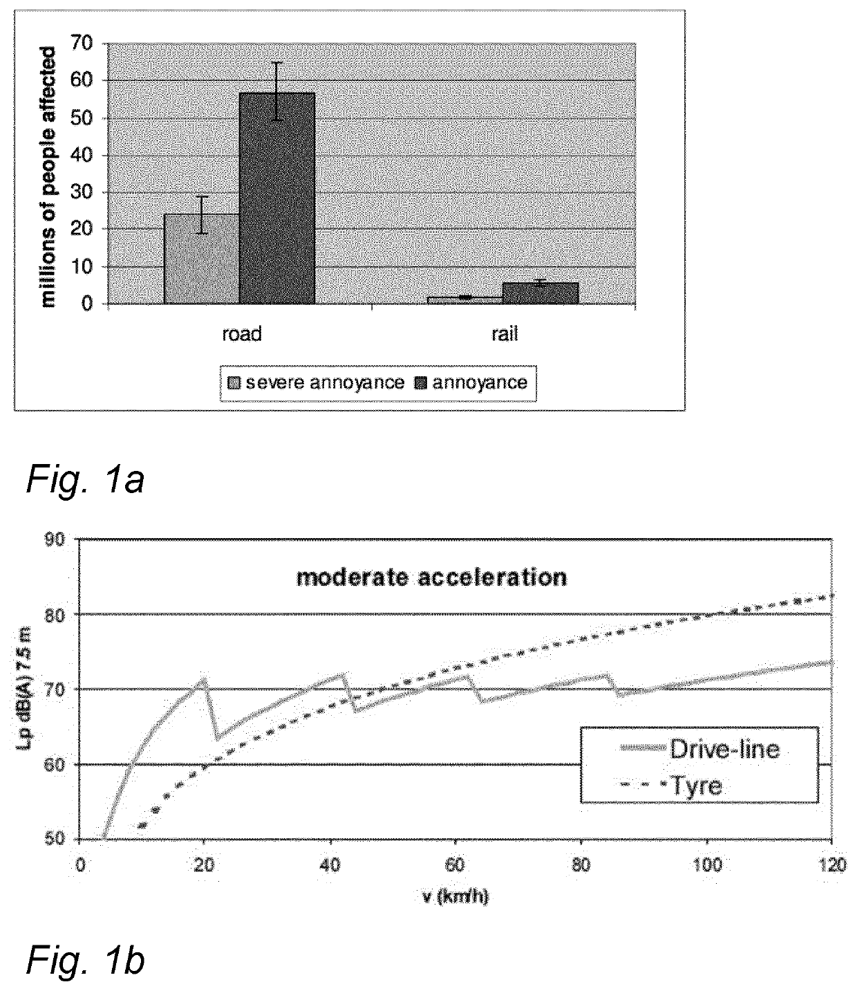
a technology of traffic rerouting and lighting system, which is applied in surveying and navigation, instruments, navigation instruments, etc., can solve the problems of more noise a vehicle produces, more noise, and blasted stones on the pavement, so as to improve the calculated noise metrics, reduce noise pollution, and improve the effect of distribution

Active Publication Date: 2020-04-23
SIGNIFY HLDG BV
View PDF0 Cites 3 Cited by
  • Summary
  • Abstract
  • Description
  • Claims
  • Application Information

AI Technical Summary

Benefits of technology

[0019]wherein the vehicle routing device comprises a memory arranged to store a digital map of the environment, the processor circuit of the vehicle routing device being arranged to estimate future noise metrics as a result of rerouting according to the traffic rerouting signal, transmitting the traffic rerouting signal being dependent upon the estimated future noise metrics improving the calculated noise metrics.
[0020]Through the combination of acoustic sensors distributed over an environment, say over a city and a vehicle routing device rerouting signals can be generated to better distribute or reduce the noise pollution.

Problems solved by technology

Noise has always been an important environmental problem for humankind Already in the ancient Rome, rules were set regarding the noise emitted from the ironed wheels of wagons, which battered the stones on the pavement.
However, over time the noise problems became more severe, due to the modernization of traffic e.g., aircraft, trains, cars and heavily laden lorries with diesel engines.
The higher its speed, the more noise a vehicle produces.
At lower speeds driveline noise predominates, with the noise of tire-road contact becoming most important as speed increases.
For example, sound reflecting windows, walls or other types of materials are used to absorb sound waves, but have the disadvantage of changing the cityscape.
In the past other solutions / methods were also tried, such as noise regulations for traffic users but they may fail due to unrealistic laboratory conditions, which do not reflect actual, real-life, traffic situations.

Method used


Image

  • Lighting system with traffic rerouting functionality
  • Lighting system with traffic rerouting functionality
  • Lighting system with traffic rerouting functionality

Examples


Embodiment Construction

[0059]While this invention is susceptible of embodiment in many different forms, there are shown in the drawings and will herein be described in detail one or more specific embodiments, with the understanding that the present disclosure is to be considered as exemplary of the principles of the invention and not intended to limit the invention to the specific embodiments shown and described.

[0060]In the following, for the sake of understanding, elements of embodiments are described in operation. However, it will be apparent that the respective elements are arranged to perform the functions being described as performed by them.

[0061]Further, the invention is not limited to the embodiments, and the invention lies in each and every novel feature or combination of features described herein or recited in mutually different dependent claims.

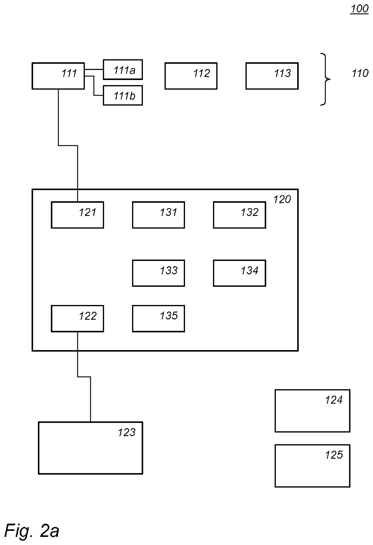
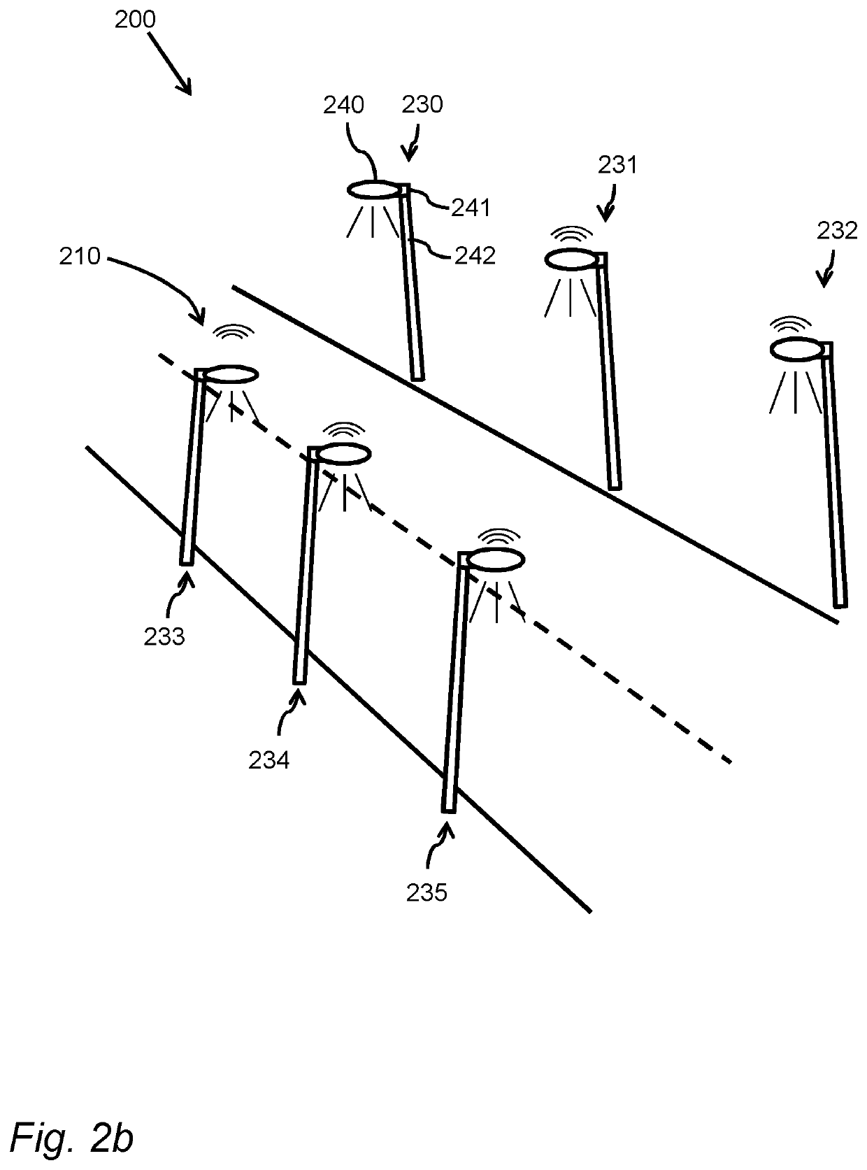
[0062]FIG. 2a schematically shows an example of an embodiment of a lighting system 100. The lighting system is arranged for illuminating an environment...


PUM


Abstract

A lighting system for illuminating an environment, the lighting system comprising a plurality of lighting modules (111, 112, 113), the lighting modules comprising a light source (111a) for emitting light, illuminating an area, an acoustic sensor (111b) arranged for sensing noise in the area, a network interface configured to allow the lighting module to send noise data via a network, and a vehicle routing device (120) comprising: a first network interface (121) configured to receive noise data from the plurality of lighting modules via the network, a processor circuit arranged to calculate noise metrics for different regions (341-344) in the environment from the received noise data, compare the calculated noise metric with noise metric threshold values, dependent upon the calculated noise metric exceeding a noise metric threshold value for a particular region, generating a traffic rerouting signal, said traffic rerouting signal causing a traffic routing system to reroute traffic away from said particular region.

Description

FIELD OF THE INVENTION[0001]The invention relates to a lighting system for illuminating an environment, a vehicle routing device, a lighting method for illuminating an environment, and a computer readable medium.BACKGROUND[0002]Noise has always been an important environmental problem for humankind Already in the ancient Rome, rules were set regarding the noise emitted from the ironed wheels of wagons, which battered the stones on the pavement. In Medieval Europe, horse carriages and horseback ridings were not allowed during nighttime. However, over time the noise problems became more severe, due to the modernization of traffic e.g., aircraft, trains, cars and heavily laden lorries with diesel engines.[0003]The extent of the noise problem nowadays is large; it has been shown that in the countries of EU-25 during the daytime about 44% of the population (210 million people) and during the nighttime about 30% of the population (140 million people) are exposed to road traffic noise with ...

Claims


Application Information

Patent Timeline
Patent Type & Authority Applications(United States)
IPC IPC(8): G08G1/01G08G1/0968G08G1/015G08G1/087G01C21/34
CPCG08G1/096827G08G1/087G08G1/09685G08G1/0145G08G1/0116G01C21/3461G08G1/096816G08G1/015G01C21/3492G08G1/0133G08G1/082G08G1/095
Inventor VONCKEN, RALF GERTRUDA HUBERTUSLEKSE, DOMINIKASINITSYN, ALEXANDRE GEORGIEVICHDE VRIES, JUDITH HENDRIKA MARIAVERHOEVEN, TOM
Owner SIGNIFY HLDG BV
Why Eureka
Try Eureka