
Electronic device and method for transmitting uplink reference signal

Active Publication Date: 2020-04-23
SAMSUNG ELECTRONICS CO LTD
View PDF0 Cites 10 Cited by
  • Summary
  • Abstract
  • Description
  • Claims
  • Application Information

AI Technical Summary

Benefits of technology

The patent describes an electronic device that sends a specific signal to a base station to measure the quality of the communication. This allows the base station to support multiple antennas and improve efficiency. The device uses a special switch to manage the signal transmission and calibration, which helps to reduce wires and switches. The technical effects of this patent are improved communication accuracy and efficiency.

Problems solved by technology

A precoding scheme used when a base station transmits a Downlink (DL) Multiple Input Multiple Output (MIMO) signal to an electronic device in a Long Term Evolution (LTE) communication environment depends only on Precoding Matrix Indicator (PMI) or Channel Quality Indicator (CQI) information, fed back by the electronic device, and thus has a limit on performance.
However, according to a limit mounting space of the electronic device, a method of implementing the SRS switching technology while minimizing the additional switch or wire may be required.

Method used


Image

  • Electronic device and method for transmitting uplink reference signal
  • Electronic device and method for transmitting uplink reference signal
  • Electronic device and method for transmitting uplink reference signal

Examples


Embodiment Construction

[0027]FIGS. 1 through 7, discussed below, and the various embodiments used to describe the principles of the present disclosure in this patent document are by way of illustration only and should not be construed in any way to limit the scope of the disclosure. Those skilled in the art will understand that the principles of the present disclosure may be implemented in any suitably arranged system or device.

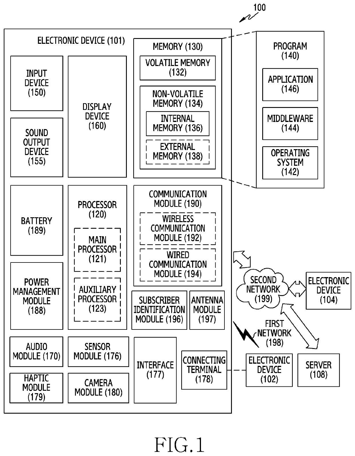
[0028]FIG. 1 illustrates a block diagram of an electronic device 101 in a network environment 100 according to various embodiments. Referring to FIG. 1, the electronic device 101 in the network environment 100 may communicate with an electronic device 102 via a first network 198 (e.g., a short-range wireless communication network), or an electronic device 104 or a server 108 via a second network 199 (e.g., a long-range wireless communication network). According to an embodiment, the electronic device 101 may communicate with the electronic device 104 via the server 108. According t...


PUM


Abstract

An electronic device including: an antenna; a first switch functionally connected to the antenna and configured to perform switching to connect the antenna with a transmission path or a reception path; a first filter and a first amplifier configured to form the reception path; a second filter and a second amplifier configured to form the transmission path; a Radio Frequency Integrated Circuit (RFIC) connected to the reception path and the transmission path and configured to process an RF signal; and at least one processor configured to control the RFIC and the first switch such that a transmission signal generated by the RFIC is radiated from the antenna via the transmission path.

Description

CROSS-REFERENCE TO RELATED APPLICATIONS[0001]This application is based on and claims priority under 35 U.S.C. 119 to Korean Patent Application No. 10-2018-0124501, filed on Oct. 18, 2018, in the Korean Intellectual Property Office, the disclosure of which is herein incorporated by reference in its entirety.BACKGROUND1. Field[0002]The disclosure relates to an electronic device and a method for transmitting an uplink reference signal.2. Description of Related Art[0003]The above information is presented as background information only to assist with an understanding of the disclosure. No determination has been made, and no assertion is made, as to whether any of the above might be applicable as prior art with regard to the disclosure.[0004]To meet the demand for wireless data traffic having increased since deployment of 4G communication systems, efforts have been made to develop an improved 5G or pre-5G communication system. Therefore, the 5G or pre-5G communication system is also calle...

Claims


Application Information

Patent Timeline
IPC IPC(8): H04B1/401H04B1/00H04B1/44H04L25/02H04L5/00
CPCH04L5/0051H04B1/0057H04L25/0226H04B1/44H04B1/401H04B1/48H04B7/0602H04B17/14H04W52/146H04W52/325H04W52/52H04B17/21H04B17/309H04B7/0413
Inventor CHO, NAMJUNKIM, GEUNWOO
Owner SAMSUNG ELECTRONICS CO LTD
Learn More