Adaptive control of ladar systems using spatial index of prior ladar return data

a technology of spatial index and ladar system, applied in the direction of reradiation, measurement device, instruments, etc., can solve the problems of affecting the accuracy of the analysis operation

Active Publication Date: 2020-04-30
AEYE INC
View PDF4 Cites 26 Cited by
  • Summary
  • Abstract
  • Description
  • Claims
  • Application Information

AI Technical Summary

Benefits of technology

[0004]Safe autonomy in vehicles, whether airborne, ground, or sea-based, relies on rapid precision, characterization of, and rapid response to, dynamic obstacles. Ladar systems are commonly used for detecting such obstacles. As used herein, the term “ladar” refers to and encompasses any of laser radar, laser detection and ranging, and light detection and ranging (“lidar”).
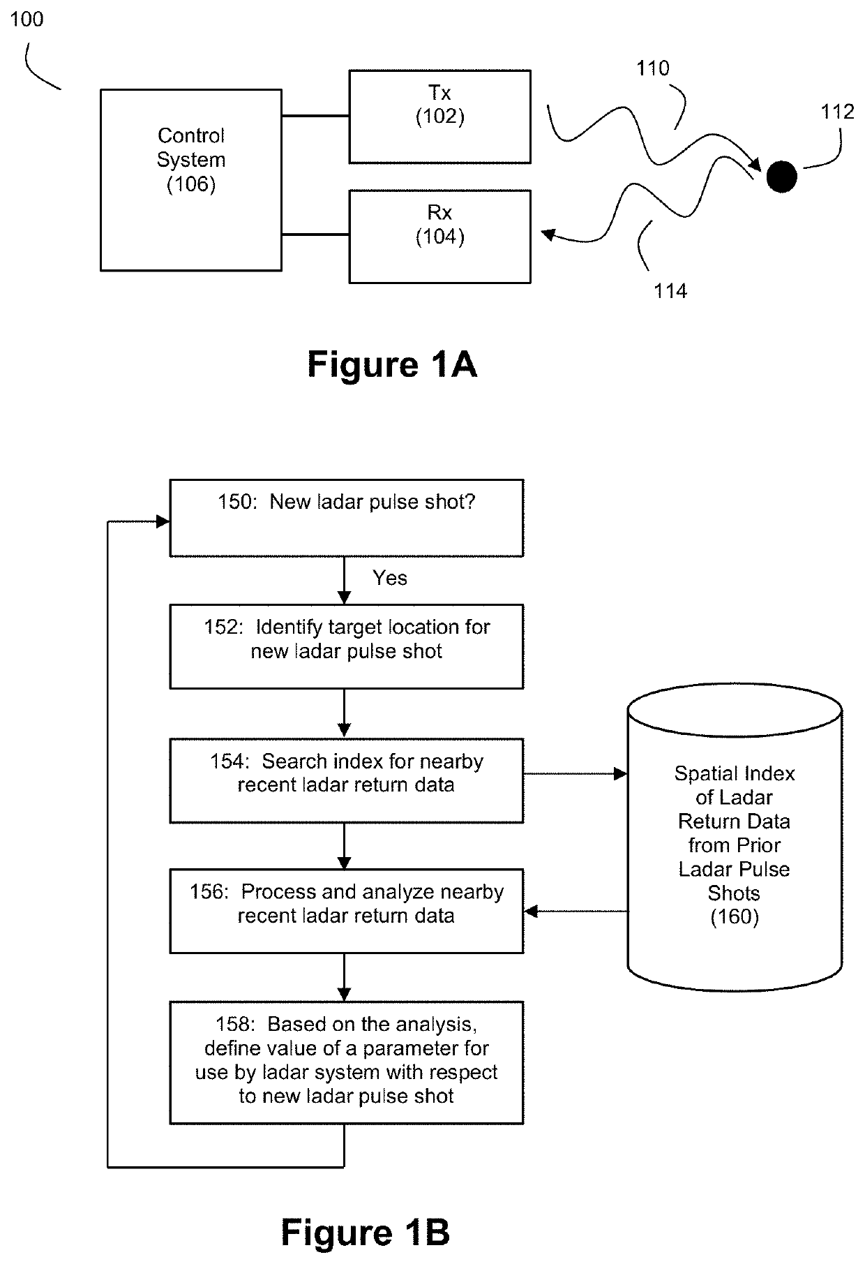
[0007]Accordingly, in an example embodiment, the inventors disclose a ladar system that adapts shot energy for the ladar transmitter as a function of prior ladar return data so that the ladar system can achieve a more uniform illumination (or smoother illumination) of nearby parts of the field of view. Accordingly, the ladar transmitter may adjust its shot energy on a shot-by-shot basis for interrogating range points that are near each other in the field of view. It should be understood that the goal of increasing the uniformity or smoothness of illumination by the ladar transmitter over a region of nearby portions of the field of view does not require the ladar transmitter to produce equal illumination for each range point in that region. Instead, it should be understood that increased uniformity or smoothness is a soft term that relates to a gradient of intensities that is sufficiently mild so as to not unduly erode the performance of object classification algorithms (many of which may be powered by machine learning techniques, edge detection processes, bounding boxes, and others).

Problems solved by technology

However, it is sometimes the case that artifacts and noise may be present in the ladar return data and ladar images used for object detection with autonomous vehicles.
Such artifacts and noise can hamper the analysis operations that are performed on the ladar return data.
However, the presence of artifacts and noise in the ladar images can corrupt the training process and / or the classification process, which can lead to a risk of misclassification during vehicle operation.
The inventors believe that some of the artifacts and noise present in ladar return data arise from non-uniform illumination of the field of view by the ladar system.
Furthermore, a number of factors can make the goal of increasing the uniformity illumination technically challenging.
Because current lasers operate at a fast re-fire rate (e.g., 100,000 to 3,000,000 shots per second is typical), this means that using ladar return data to adapt the ladar system with low latency is a computationally-challenging task.

Method used


Image

  • Adaptive control of ladar systems using spatial index of prior ladar return data
  • Adaptive control of ladar systems using spatial index of prior ladar return data
  • Adaptive control of ladar systems using spatial index of prior ladar return data

Examples


example use cases

[0119]The left frame of FIG. 8 shows an example ladar return image 800 that is derived from a ladar system where no adaptive feedback control to achieve a more uniform illumination of the field of view is not employed. Image 800 is a 2D projected image of the intensity map in the ladar point cloud produced by a ladar system lacking adaptive feedback for a given frame. The right frame of FIG. 8 shows a camera image 802 of this same scene. As can be seen in ladar image800, there are several vertical stripes that are present, and these stripes are not present in the environment. Instead, these stripes are due to artifacts in the ladar return data that arise, at least in part, due to non-uniformities in the shot energy of the transmitted ladar pulses.

[0120]By contrast, FIG. 9 shows an intensity map, 3D perspective point cloud where the ladar system employs adaptive feedback control of shot energy using the spatial index 160 and FIG. 3A process flow (left frame) as well as a 2D image of ...


PUM


Abstract

Disclosed herein are examples of ladar systems and methods where data about a plurality of ladar returns from prior ladar pulse shots gets stored in a spatial index that associates ladar return data with corresponding locations in a coordinate space to which the ladar return data pertain. This spatial index can then be accessed by a processor to retrieve ladar return data for locations in the coordinate space that are near a range point to be targeted by the ladar system with a new ladar pulse shot. This nearby prior ladar return data can then be analyzed by the ladar system to help define a parameter value for use by the ladar system with respect to the new ladar pulse shot. Examples of such adaptively controlled parameter values can include shot energy, receiver parameters, shot selection, camera settings, and others.

Description

CROSS-REFERENCE AND PRIORITY CLAIM TO RELATED PATENT APPLICATION[0001]This patent application claims priority to U.S. provisional patent application Ser. No. 62 / 750,540, filed Oct. 25, 2018, and entitled “Adaptive Control of Ladar Systems Using Spatial Index of Prior Ladar Return Data”, the entire disclosure of which is incorporated herein by reference.[0002]This patent application also claims priority to U.S. provisional patent application Ser. No. 62 / 805,781, filed Feb. 14, 2019, and entitled “Adaptive Control of Ladar Systems Using Spatial Index of Prior Ladar Return Data”, the entire disclosure of which is incorporated herein by reference.[0003]This patent application is also related to (1) U.S. patent application Ser. No. ______ filed this same day, and entitled “Adaptive Control of Ladar Shot Energy Using Spatial Index of Prior Ladar Return Data” (said application being identified by Thompson Coburn Attorney Docket Number 56976-185809), (2) U.S. patent application Ser. No. ___...

Claims


Application Information

Patent Timeline
Patent Type & Authority Applications(United States)
IPC IPC(8): G01S7/4863G01S17/10G01S7/484
CPCG01S7/4863G01S7/484G01S17/10G01S17/89G01S17/931G01S17/42G01S7/4802G01S17/93G01S17/006G01S17/46G01S7/4817G01S7/4861G01S17/58G01S7/4816G01S7/4808G01S7/4814
Inventor DUSSAN, LUIS CARLOSSTEINHARDT, ALLANPRESUTTI, FEDERICOBENSCOTER, JOEL DAVID
Owner AEYE INC
Why Eureka
Try Eureka