
Self-Configuring Peripheral Module

a peripheral module and self-configuration technology, applied in error detection/correction, program control, instruments, etc., can solve the problems of actuator not even responding to the change in supply potential, actuators not responding yet, and the effect of controlled process is often too small, so as to simplify the operation of a peripheral module

Active Publication Date: 2020-04-30
SIEMENS AG
View PDF0 Cites 0 Cited by
  • Summary
  • Abstract
  • Description
  • Claims
  • Application Information

AI Technical Summary

Benefits of technology

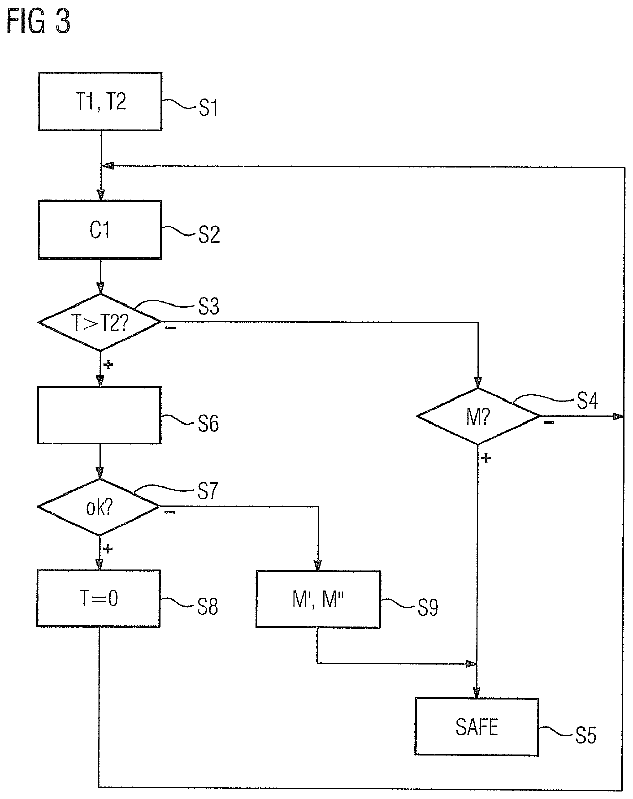
The present invention simplifies the commissioning of a peripheral module by automatically and reliably determining the necessary time interval. This is achieved by repeatedly supplying the base voltage value, modifying the supply potential, and acquiring the start time and response time, resulting in a provisional time interval. The peripheral module then statistically evaluates the provisional time intervals to ascertain the valid time interval. This procedure improves accuracy and reliability, and reduced laborious and time-consuming tasks for operators. Additionally, the invention allows for conditional validation of the valid time interval, further reducing the likelihood of incorrect detections.

Problems solved by technology

While it is indeed possible to specify the time interval with a maximum possible value (for example 2 seconds) and so set a fixed time interval, this would, however, result in the modified voltage value being output to the actuator for an appreciable time interval that is often much too long for an individual case.
In particular, it would often result in the actuator actually responding to the change in the supply potential.
On the other hand, due to the sluggishness of the actuator, it may for example happen that the actuator has not yet even responded during the defined time interval.
Even if the actuator actually responds, the effect on the controlled process is nevertheless often sufficiently small provided the time interval is also sufficiently short.
This would, however, result in the modified voltage value being output to the sensor for an appreciable time interval that is often much too long for an individual case.
In particular, this would often result in the sensor itself not being able to respond during this time interval to the signal it is actually intended to acquire.
This procedure is, on the one hand, time-consuming and thus also costly and, on the other hand, error-prone.

Method used


Image

  • Self-Configuring Peripheral Module
  • Self-Configuring Peripheral Module
  • Self-Configuring Peripheral Module

Examples


Embodiment Construction

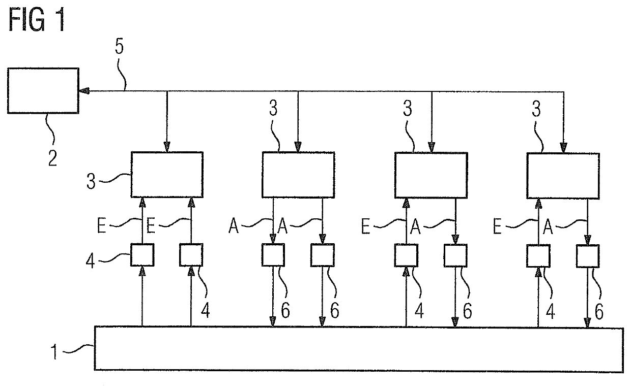
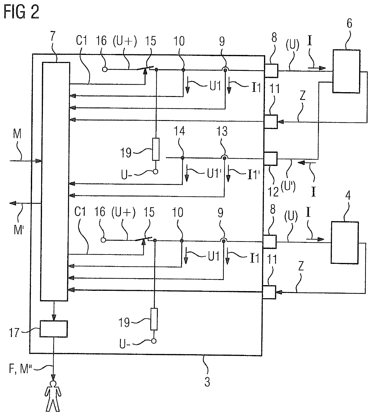
[0031]As shown in FIG. 1, a technical industrial process 1 is controlled or at least partially controlled via a programmable controller. The technical industrial process 1 may in principle be of any desired nature. The programmable controller has a central unit 2 and peripheral modules 3. The peripheral modules 3 receive input variables E from the process 1 via sensors 4 and relay them, for example, via a bus system 5, to the central unit 2. The sensors 4 may, for example, be emergency stop switches. They may, however, also be other sensors. The central unit 2, taking account of the input variables E transferred thereto, ascertains output variables A for the process 1 and outputs them, for example, via the bus system 5, to the peripheral modules 3. The peripheral modules 3 thereupon accordingly drive actuators 6, via which the process 1 is influenced. The actuators 6 may, for example, control a power supply of the process 1. Other actions are, however, also possible. The sensors 4 a...


PUM


Abstract

A peripheral module of a programmable controller and method for operating the peripheral module, wherein in a calibration mode a base voltage value is supplied by the peripheral module to a terminal via a switching device, the supply potential is changed at a start time by the peripheral module to the modified value and a response time at which the expected change occurs is acquired, and the valid time interval is ascertained by the peripheral module utilizing the start time and the response time.

Description

BACKGROUND OF THE INVENTION1. Field of the Invention[0001]The present invention relates to an operating method for a peripheral module of a programmable controller, where the peripheral module outputs, via a terminal of the peripheral module, a supply potential and, in this respect, an associated supply current to a field unit connected to the peripheral module, where, in a normal mode, the supply potential has a base voltage value and, in this respect, the supply current has a base current value, where the peripheral module changes over from time-to-time from normal mode into a test mode, in which the peripheral module changes the supply potential from the base voltage value to a modified voltage value by driving a switching device that is upstream of the terminal within the peripheral module for a defined valid time interval, checks whether, once the defined time interval has elapsed, an expected change has occurred due to the modification of the supply potential, changes back ove...

Claims


Application Information

Patent Timeline
Patent Type & Authority Applications(United States)
IPC IPC(8): G06F13/372G06F13/42G06F13/16G06F11/30G06F11/22
CPCG06F11/221G06F13/1668G06F13/4256G06F13/372G06F11/3013G05B19/054G05B2219/1103G05B19/0425
Inventor HARITOUNIAN, SEVAN
Owner SIEMENS AG
Learn More