
Attenuation of load oscillations without additional measuring means on the load side

a technology of load oscillation and measuring means, which is applied in the direction of electric programme control, program control, instruments, etc., can solve the problems of difficult control technology management, frequent disturbance of load oscillation, and complex controllers, and achieve simple commissioning and good control results

Active Publication Date: 2020-01-07
SIEMENS AG
View PDF26 Cites 0 Cited by
  • Summary
  • Abstract
  • Description
  • Claims
  • Application Information

AI Technical Summary

Benefits of technology

The present invention provides a solution to attenuate low-frequency load oscillations for drives with motor and load, which is simple to commission and has good control results. This solution does not require additional measurement devices and is more robust than other solutions. The load properties no longer have a role to play, and the path has only a limited effect on the natural frequency. The method / device can be integrated with existing attenuation methods with minimal adaptations.

Problems solved by technology

These load oscillations are frequently very disruptive and are difficult to manage with control technology.
These controllers are however frequently so complex that it is only possible for them to be used by academic closed-loop control specialists.
Such state controllers therefore appear unsuitable for a broad product solution, above all in respect of simple commissioning.
If such automatic commissioning is unsuccessful manual intervention is only then possible by specialists.
One problem in commissioning a state controller is that a number of feedbacks have to be adjusted simultaneously, since the feedbacks influence each other.
This problem also occurs in principle when values to be connected to the torque are created, since a torque controller partly regulates away the value connected again and thus influences it.
A good fault behavior is thus hardly successful.
These approaches are complex and less robust in relation to path changes.
Thereby a similar complex structure is obtained to that of the classic state controller, which is difficult to adjust.
But this too is problematic, since the control path here has three poles at the stability edge and does not have any zero point, which makes a stable control possible only in a narrow band.
This makes commissioning difficult.
The consequence of this is that movement processes last comparatively long and that only a low control rigidity can be achieved.
In some cases however active attenuation is not possible or is only possible with great difficulty.

Method used


Image

  • Attenuation of load oscillations without additional measuring means on the load side
  • Attenuation of load oscillations without additional measuring means on the load side
  • Attenuation of load oscillations without additional measuring means on the load side

Examples


Embodiment Construction

[0045]Although the invention has been illustrated and described in greater detail by the preferred exemplary embodiments, the invention is not restricted by the disclosed examples. Variations herefrom can be derived by the person skilled in the art, without departing from the scope of the invention, as is defined by the claims given below.

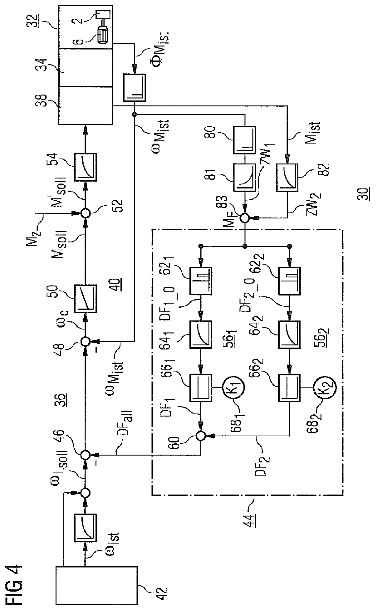
[0046]Shown in greater detail in FIG. 4 is a drive control device 30 of a controlled drive 32 with motor 6 and load 2, wherein parts of this drive control device 30 are presented in greater detail. A commercially-available drive control device 30 has a final control element 34, for example a power converter, in particular a self-commutated pulse-controlled inverter, and a closed-loop controller 36. This closed-loop controller 36 consists for example of a motor model with current controller 38, a speed control circuit 40 and a position control circuit 42. These control circuits 38,40 and 42 form a control attenuator passage. I.e. the position contro...


PUM


Abstract

A method for attenuating load oscillations in a load mechanism having a controlled drive, wherein a load is coupled mechanically to a motor via a spring element, includes determining an actual motor torque value, determining an actual angular velocity value, determining a motor inertial torque, calculating a spring torque from the actual angular velocity value, the motor inertial torque and the actual motor torque value, and supplying the calculated spring torque to an attenuator connection for attenuating the load oscillations.

Description

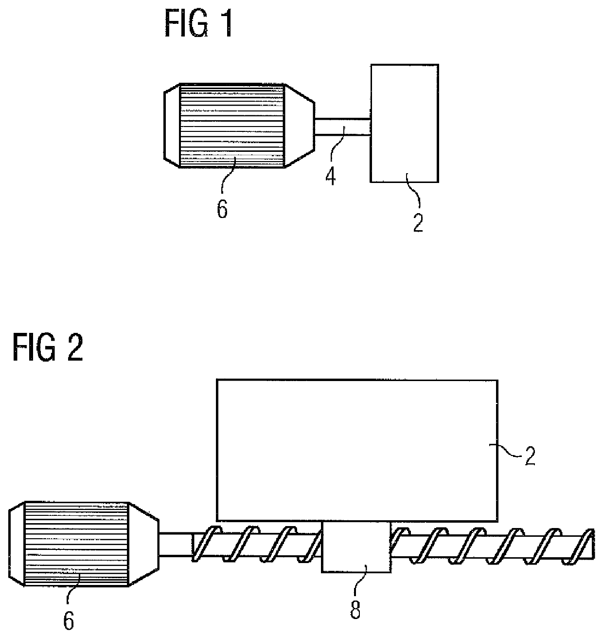
CROSS-REFERENCES TO RELATED APPLICATIONS[0001]This application is the U.S. National Stage of International Application No. PCT / EP2016 / 070486 filed Aug. 31, 2016, which designated the United States and has been published as International Publication No. WO 2017 / 045920 and which claims the priority of European Patent Application, Serial No. 15185655.6, filed Sep. 17, 2015, pursuant to 35 U.S.C. 119(a)-(d).BACKGROUND OF THE INVENTION[0002]The invention relates to a method and to a device that is especially suitable for carrying out the method, for attenuation of load oscillations in a load mechanism with a controlled drive, in which a load is coupled mechanically to a motor via a spring element.[0003]In drive control a load 2 is frequently moved via a shaft 4 by a controlled drive, consisting of a final control element, for example a power converter, and a motor 6. Such a drive configuration is shown in greater detail in FIG. 1. A further drive configuration is illustrated schematicall...

Claims


Application Information

Patent Timeline
Patent Type & Authority Patents(United States)
IPC IPC(8): G05B19/404B62D5/04F16F15/00G05B19/19
CPCG05B19/19B62D5/0472G05B19/404F16F15/002G05B2219/49054G05B2219/49048
Inventor KÜNZEL, STEFANHAMM, CARSTEN
Owner SIEMENS AG
Learn More