Equipment for machining surfaces, in particular solid surfaces, in particular for machining rumble strips

a technology for machining surfaces and solid surfaces, applied in the direction of stone-like material working tools, roads, roads, etc., can solve the problems of large cost (both purchase and maintenance and/or management costs), unaffordable amortization costs, and small-to-medium companies, and achieve simple and reliable adjustment, simple and reliable, and immediate and therefore affordable operations

Active Publication Date: 2020-05-07
L M DEI F LLI MONTICELLI
View PDF1 Cites 2 Cited by
  • Summary
  • Abstract
  • Description
  • Claims
  • Application Information

AI Technical Summary

Benefits of technology

[0066]It has therefore been shown by the detailed description above of the embodiments of the present invention depicted in the drawings, that the present invention allows the preset objects to be reached and/or overcome, or at least the drawbacks typical of the solutions according to the known art, to be minimized.
[0067]In particular, according to the present invention, a normal milling machine may be readapted as apparatus for making sound strips and readapted again as a normal milling machine by means of simple, immediate and therefore affordable operations. Moreover, t

Problems solved by technology

However, although the equipments of known type can be appreciated from different points of view, same are affected by several different drawbacks.
As indicated above, a first drawback relates to the poor versatility of the equipments of known type which, being dedicated only to (and usable exclusively for) making sound strips, often results in unaffordable amortization costs, especially for small-to-medium companies.
Moreover, in addition to resulting in significant costs (both purchase and maintenance and/or management costs), the equipments of known type have significant volumes and sizes with subsequent, just as significant logistic problems associated in particular with transport and storage.
Moreover, it must not

Method used


Image

  • Equipment for machining surfaces, in particular solid surfaces, in particular for machining rumble strips
  • Equipment for machining surfaces, in particular solid surfaces, in particular for machining rumble strips
  • Equipment for machining surfaces, in particular solid surfaces, in particular for machining rumble strips

Examples


Embodiment Construction

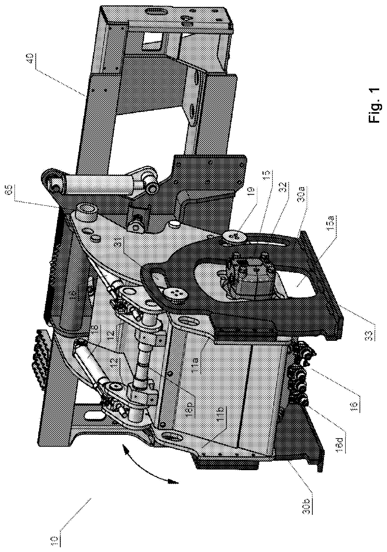
[0039]The present invention particularly and effectively applies in the case of equipment for milling solid surfaces and / or floors; this therefore is the reason why the present invention is described below with particular reference to the application thereof in the case of milling equipments for milling or milling machine.

[0040]The possible applications of the present invention in any case are not limited to the case of milling equipments; contrarily, the present invention is effectively and conveniently applied in various equipments such as for example, pit and / or trench digging equipments or in any case, for machining and / or demolishing surfaces, in particular solid surfaces.

[0041]As indicated above, two arrangements are possible in case of the equipment according to the present invention, each provided for at least one possible use of the equipment.

[0042]A first use relates to milling solid surfaces at a predefined, substantially constant depth which can be preset as liked and / or...


PUM

PropertyMeasurementUnit
Electrical resistanceaaaaaaaaaa
Transmissionaaaaaaaaaa
Depthaaaaaaaaaa

Abstract

Equipment for machining solid surfaces such as for example, surfaces made of asphalt or concrete or similar solid materials, in particular for making sound strips, said equipment comprising rotating machining or digging means carried by a main frame, and rotating means which engage said main supporting frame, wherein the rotation of said rotating means in a predefined direction of rotation results in said main supporting frame being rotated alternately in two opposite directions of rotation.

Description

TECHNICAL FIELD OF THE PRESENT INVENTION[0001]The present invention relates to the machining of surfaces, in particular of solid floors such as for example, floors made of concrete, asphalt or similar solid materials. The present invention in particular relates to an equipment for making sound strips in surfaces and / or floors of the aforesaid type. In detail, the present invention relates to an equipment of the aforesaid type which allows making said sound strips by means of rotating milling means, moreover wherein the equipment allows executing normal milling operations at substantially constant and adjustable depth according to needs and / or circumstances.BACKGROUND ART[0002]The definition “sound strips” commonly identifies the irregularities intentionally obtained on the road surfaces in order to generate a sudden change of the guiding perception by the driver of a vehicle, for example a motor vehicle but also a motorcycle or also a heavy-duty vehicle (trucks or the like). Practic...

Claims


Application Information

Patent Timeline
IPC IPC(8): E01C23/088B28D1/18E01C23/12E01C23/09
CPCB28D1/18E01C23/127E01C23/0993E01C23/088E02F3/183E02F3/188E01F9/529E02F3/20E02F3/246E02F3/3414E02F3/3609E02F3/96
Inventor RISI, MIRCO
Owner L M DEI F LLI MONTICELLI
Why Eureka
Try Eureka