Optical radar device

a radar device and optical technology, applied in the direction of measurement devices, instruments, telescopes, etc., can solve the problems of large-scale and expensive mechanical systems for scanning targets with laser beams, emitted laser beams of weaker intensity, and distance measurement accuracy degradation, etc., to achieve a wide incidence-angle range

Active Publication Date: 2020-05-07
SHARP KK
View PDF10 Cites 1 Cited by
  • Summary
  • Abstract
  • Description
  • Claims
  • Application Information

AI Technical Summary

Benefits of technology

[0025]An aspect of the present invention can provide a technology in flash LiDAR applicable to a wide incidence-angle range.
[0026]Another aspect of the present invention enables preferable filtering in either flash LiDAR or scanning LiDAR.

Problems solved by technology

Many scanning LiDAR systems that can acquire high beam intensity on the target have been developed these days, but they are large-sized and expensive to involve a mechanical system for scanning a target with a laser beam.
However, a flash LiDAR system emits a laser beam of weaker intensity to a target than a scanning LiDAR system.
Thus, the signal intensity decreases when the distance to a target increases, so that the distance measurement accuracy degrades.

Method used


Image

  • Optical radar device
  • Optical radar device
  • Optical radar device

Examples


embodiment 1

[0054]An embodiment of the present invention will be described as follows. Hereinbelow, for illustration purposes, components having the same functions as the components described in a specific embodiment may be denoted with the same reference signs without being described.

(Related Components of Optical Radar Device)

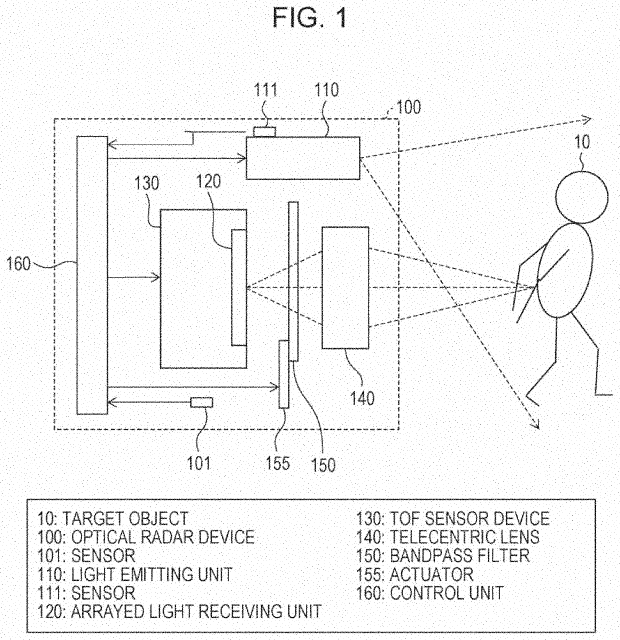
[0055]FIG. 1 is a block diagram of related components of an optical radar device 100 according to the present embodiment. As illustrated in FIG. 1, the optical radar device 100 includes a light emitting unit 110, a light receiving system, and a control unit 160, which controls the light emitting unit 110 and the light receiving system. The light emitting unit 110 diffusively radiates laser beams on an object whose range is to be determined (referred to as a “target object”, below), including a movable target, such as people and animals, and an immovable target, such as buildings and trees. In the present application, as illustrated in FIG. 1, a person 10 is described as ...

modification example of embodiment 1

[0078]Embodiment 1, in which the telecentric lens 140 and the interference bandpass filter 150 (regardless of whether it has its transmissive wavelength range adjustable) are used in combination in flash LiDAR, has been described thus far. However, the present application is not limited to Embodiment 1.

[0079]For example, in flash LiDAR, the telecentric lens 140 may be used in combination with an interference bandpass filter having its transmissive wavelength range adjustable.

[0080]As described above, the present modification example differs from Embodiment 1 only in that the interference bandpass filter in the present modification example has its transmissive wavelength range adjustable.

(Interference Bandpass Filter Capable of Adjusting Transmissive Wavelength Range)

[0081]Regardless of scanning or flash LiDAR, an infrared semiconductor laser is used as a light source by pulse driving. The peak value of the oscillation wavelength of the semiconductor laser changes due to causes such ...

embodiment 2

[0109]Another embodiment of the present invention will be described, below. For illustration purposes, components having the same function as the components described in the embodiment are denoted with the same reference signs without being repeatedly described.

[0110]Thus far, Embodiment 1, in which the telecentric lens 140 and the interference bandpass filter 150 (regardless of whether it has its transmissive wavelength range adjustable) are used in combination in flash LiDAR, and a modification example of Embodiment 1, in which the telecentric lens 140 and the interference bandpass filter 150 having its transmissive wavelength range adjustable are used in combination in flash LiDAR, have been described. However, the present application is not limited to Embodiment 1 and the modification example of Embodiment 1.

[0111]For example, an interference bandpass filter having its transmissive wavelength range adjustable may be used also in scanning LiDAR.

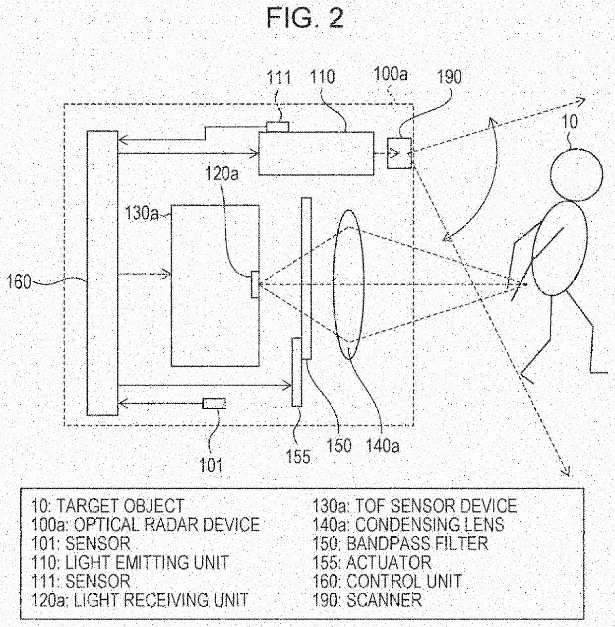
[0112]FIG. 2 is a block diagram of ...


PUM


Abstract

[Object] To provide a technology in flash LiDAR applicable to a wide incidence-angle range.
[Solution] An optical radar device (100) includes a light emitting unit (110) that diffusively radiates a laser beam, an arrayed light receiving unit (120) that receives the laser beam emitted from the light emitting unit (110) and reflected off an object whose range is to be determined (10), the arrayed light receiving unit (120) including light receiving elements arrayed two-dimensionally, and a telecentric lens (140) disposed between the object whose range is to be determined and the light receiving element.

Description

TECHNICAL FIELD[0001]The present invention relates to an optical radar device that acquires information on a distance to an object whose range is to be determined.BACKGROUND ART[0002]These days, a technology of acquiring information on a distance to a target has been increasingly important as an environment recognition technology for automobiles, robots, and other devices. Particularly, as a method of long-distance information measurement, a method of radiating a laser beam to a target and measuring time-of-flight from when the laser beam is reflected off the target until when the laser beam is returned has been widely spread, and referred to as light detection and ranging or laser imaging detection and ranging (LiDAR).[0003]Examples of a method of radiating laser beams include scanning LiDAR, for scanning a target with focused (refer to NPL 1) or band-shaped (refer to PTL 1) laser beams using a mirror or another device, and flash LiDAR, for collectively and radiating uniformly and ...

Claims


Application Information

Patent Timeline
Patent Type & Authority Applications(United States)
IPC IPC(8): G01S17/89G01S7/481G02B6/32
CPCG02B23/12G01S7/4817G01S17/89G02B6/32G01S7/4816G02B13/22G02B13/16G01S7/4811G01S17/894G02B5/28G02B5/285
Inventor TAKAHASHI, KOJIROBERTS, PETER JOHN
Owner SHARP KK
Why Eureka
Try Eureka