
EUV pattern transfer with ion implantation and reduced impact of resist residue

a technology of resist residues and ion implantation, which is applied in the field of implantation post extreme ultraviolet (euv) lithography, can solve the problems of single-line opening or adjacent-line electrical shorts after etching, micro-bridging defects, and micro-bridging defects

Active Publication Date: 2020-05-07
IBM CORP
View PDF0 Cites 5 Cited by
  • Summary
  • Abstract
  • Description
  • Claims
  • Application Information

AI Technical Summary

Benefits of technology

The patent text describes methods for preventing hard mask micro bridging effects caused by resist scumming in a semiconductor structure during extreme ultraviolet (EUV) lithography pattern transfer. The methods involve depositing a top hardmask over an organic planarization layer, patterning the photoresist using EUV lithography, and then performing ion implantation to create doped regions within the exposed top hardmask and regions of hardmask underneath resist scumming. The methods also include stripping the photoresist and selectively etching the top hardmask based on the implantation material. The technical effects of the methods are to improve the accuracy and reliability of semiconductor device fabrication processes using EUV lithography.

Problems solved by technology

During the semiconductor patterning process it is common for micro-bridging defects to occur.
Micro-bridging defects include small connections between two adjacent lines in a photo-resist pattern, which can cross-link two or more resist patterns in close proximity leading to the creation of single-line openings or adjacent-line electrical shorts after etching.
These micro-bridging defects are often caused by incomplete resist modification during EUV exposure processes.
A higher EUV radiation exposure dose can reduce micro-bridging but also results in an increased line edge roughness and undesirable resist line erosion.
In addition, a higher EUV radiation exposure dose carries a tool throughput penalty greatly affecting economic viability of EUV lithography processes.
The resist patterns of micro-bridging defects and / or increased line edge roughness and resist line erosion can cause a decrease in the production yield of advanced integrated circuits.

Method used


Image

  • EUV pattern transfer with ion implantation and reduced impact of resist residue
  • EUV pattern transfer with ion implantation and reduced impact of resist residue
  • EUV pattern transfer with ion implantation and reduced impact of resist residue

Examples


Embodiment Construction

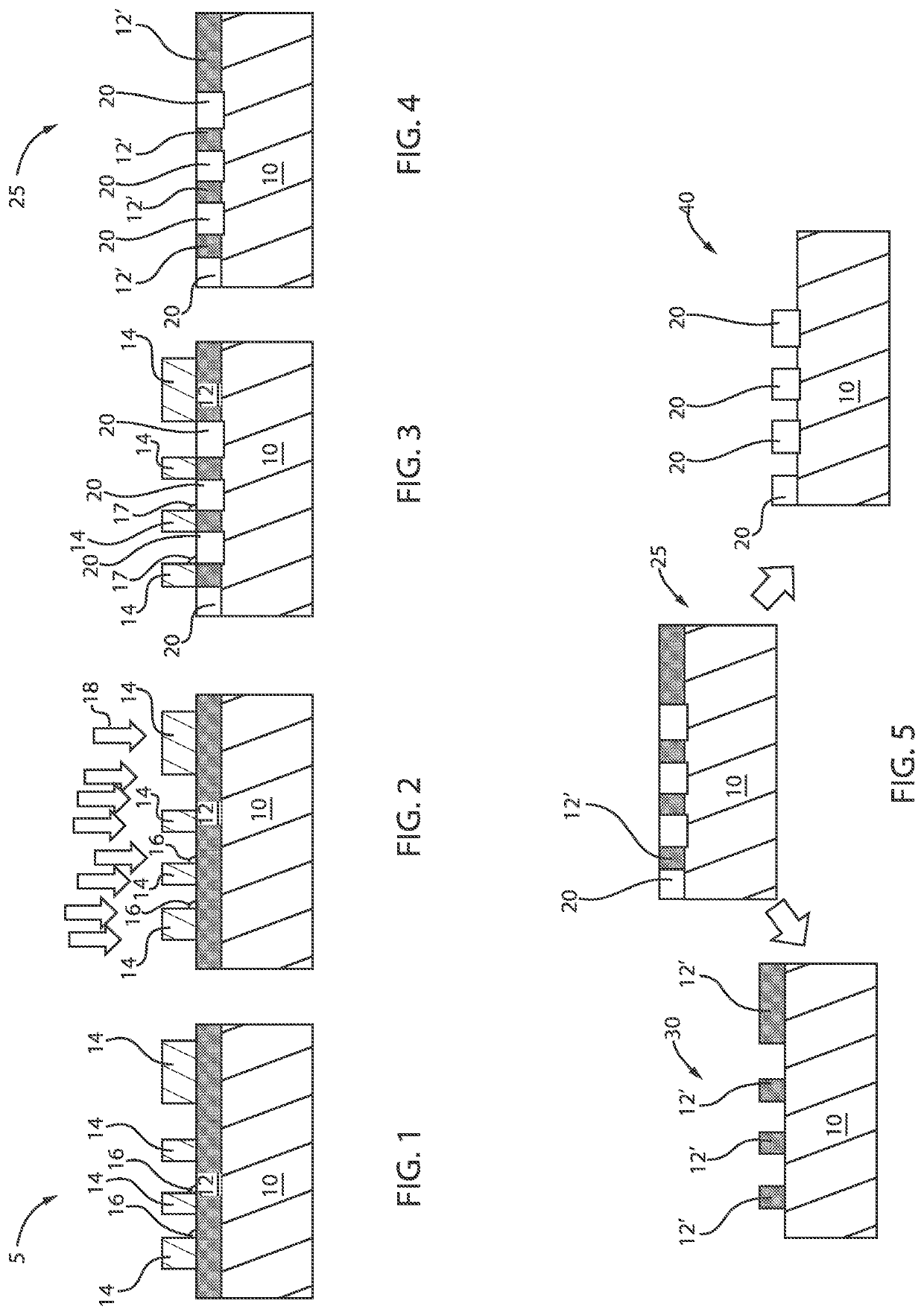
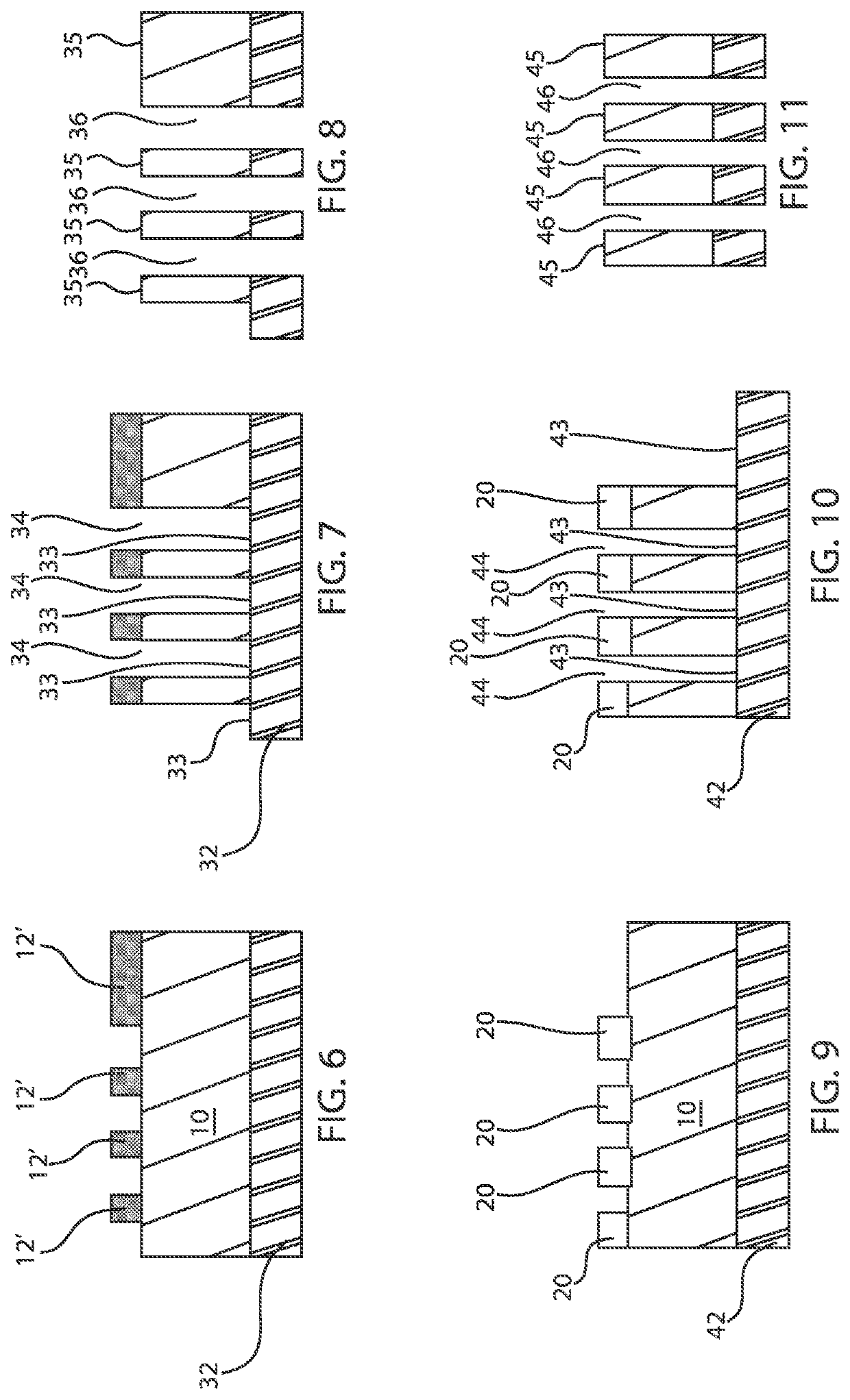
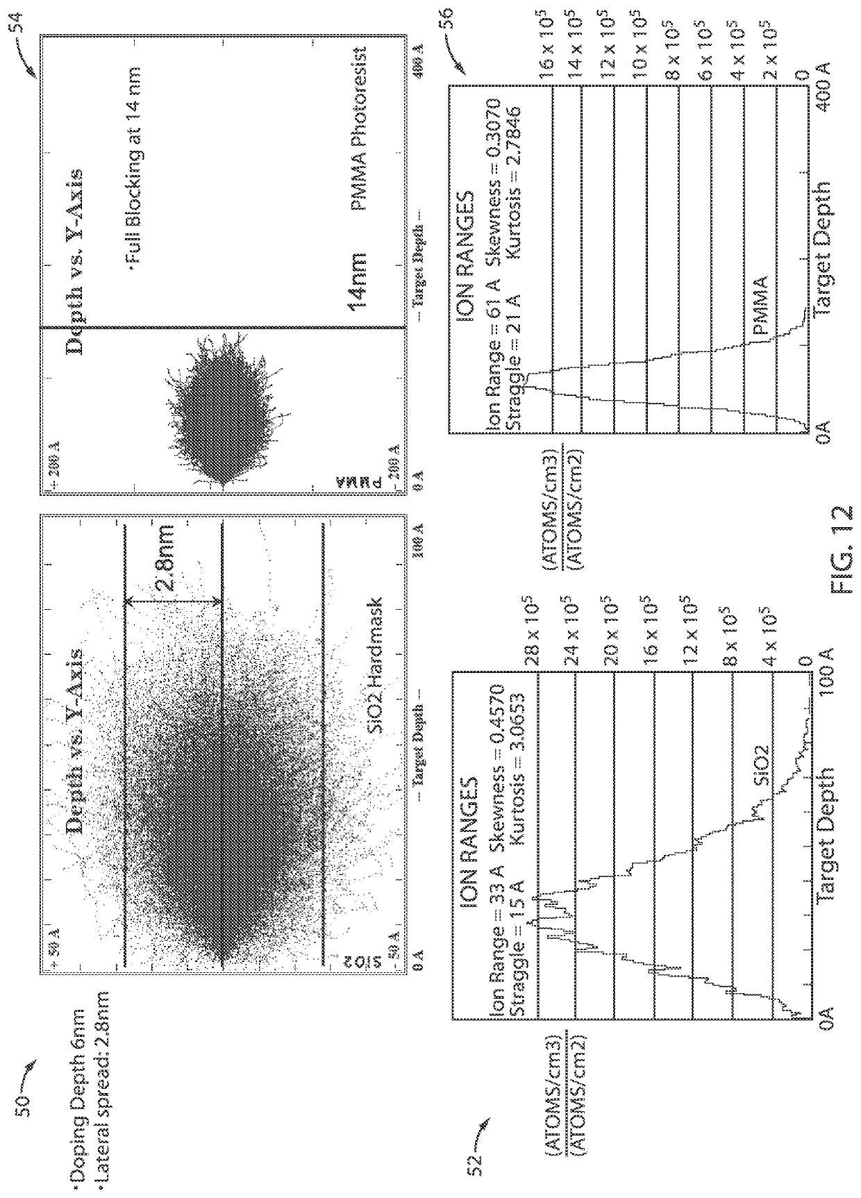
[0023]Embodiments in accordance with the present invention provide methods and devices for preventing or minimizing resist scumming and broken resist lines in semiconductor manufacturing. During the semiconductor patterning process it is common for micro-bridging defects to occur. It is particularly common for micro-bridging defects to form in the resist patterns after the EUV lithography process in advanced technology nodes, for example, nodes of approximately 7 nm and beyond. These micro-bridging or resist scumming defects are often caused by incomplete resist modification during EUV exposure processes. Micro-bridging defects include small connections between two adjacent lines in a photoresist pattern, which can connect two or more resist patterns in close proximity leading to the creation of open or short defects after etching. The open or short defects can cause a decrease in the production yield of advanced integrated circuits.

[0024]EUV lithography is a lithography technique w...


PUM


Abstract

A method is presented for amplifying extreme ultraviolet (EUV) lithography pattern transfer into a hardmask and preventing hard mask micro bridging effects due to resist scumming in a semiconductor structure. The method includes forming a top hardmask over an organic planarization layer (OPL), depositing a photoresist over the top hardmask, patterning the photoresist using EUV lithography, performing ion implantation to create doped regions within the exposed top hardmask and regions of hardmask underneath resist scumming, stripping the photoresist, and selectively etching the top hardmask by either employing positive tone or negative tone etch based on an implantation material.

Description

BACKGROUNDTechnical Field[0001]The present invention relates generally to semiconductor devices, and more specifically, to implantation post extreme ultraviolet (EUV) lithography to prevent defectivity transfer caused by resist scumming and resist line breaks.Description of the Related Art[0002]During the semiconductor patterning process it is common for micro-bridging defects to occur. It is particularly common for micro-bridging defects to form in the resist patterns after the EUV lithography process in advanced technology nodes, for example, nodes of approximately 7 nm and beyond. This is due to different physical mechanisms of EUV radiation exposure and its interaction with resist constituents as opposed to processes occurring during more common ultraviolet exposure in optical lithography. Micro-bridging defects include small connections between two adjacent lines in a photo-resist pattern, which can cross-link two or more resist patterns in close proximity leading to the creati...

Claims


Application Information

Patent Timeline
IPC IPC(8): H01L21/033H01L21/311G03F7/20H01L21/3115
CPCH01L21/0337H01L21/31155H01L21/3088H01L21/31111G03F7/2022G03F7/094G03F7/40H01L21/31116H01L21/31144
Inventor MIGNOT, YANNXU, YONGANGLUSCHENKOV, OLEG
Owner IBM CORP
Learn More