
Notification system and notification method

a technology of notification system and notification method, which is applied in the direction of charging station, electric vehicle charging technology, transportation and packaging, etc., can solve the problems of inability to detect foreign objects, inability to properly charge the power storage device mounted on the vehicle, and inability to perform foreign object detection processes, etc., to achieve the effect of restricting the power transmission

Active Publication Date: 2020-05-07
TOYOTA JIDOSHA KK
View PDF0 Cites 2 Cited by
  • Summary
  • Abstract
  • Description
  • Claims
  • Application Information

AI Technical Summary

Benefits of technology

The patent describes a notification system that alerts a user of a vehicle when a foreign object is detected on the power transmission device. This helps the user remove the foreign object before they leave the vehicle, preventing power interruptions. The system also reduces the processing load on the controller by only performing the foreign object detection process when certain conditions are met, such as when the vehicle is traveling at a high speed or when the shift range is shifted to the parking range. Overall, the notification system improves operational efficiency and safety for wireless power transmission in vehicles.

Problems solved by technology

Thus, even though a foreign object is already present when the vehicle is parked at a position capable of receiving power from the power transmission coil, the foreign object detection process will not be performed until the power transmission is started.
As a result, the power storage device mounted on the vehicle may not be charged properly.
According to the above aspect, even though the wireless communication is established between the power transmission device and the vehicle, if the first condition is not satisfied, for example, if the vehicle is traveling at a vehicle speed equal to or higher than a predetermined speed, the foreign object detection process may not be performed.

Method used


Image

  • Notification system and notification method
  • Notification system and notification method
  • Notification system and notification method

Examples


first modification

[0106]In the embodiment above, as an example, it is described that when a foreign object is detected, the foreign object detection image Im is displayed on the display device 380.

[0107]However, in certain instances, it may be preferred to display another image on the display device 380 in addition to the foreign object detection image Im. Therefore, after a foreign object is detected, if the display of the other image is requested, the size of the foreign object detection image Im may be reduced so as to save an area to display the other image, or the foreign object detection image Im and the other image may be displayed alternately.

[0108]FIG. 7 diagram illustrating an example in which an image It indicating the setting contents of timer charging (external charging to be performed according to a predetermined schedule) and a foreign object detection image Im are alternately displayed in a predetermined interval until a predetermined time has passed since the control system is switch...


PUM


Abstract

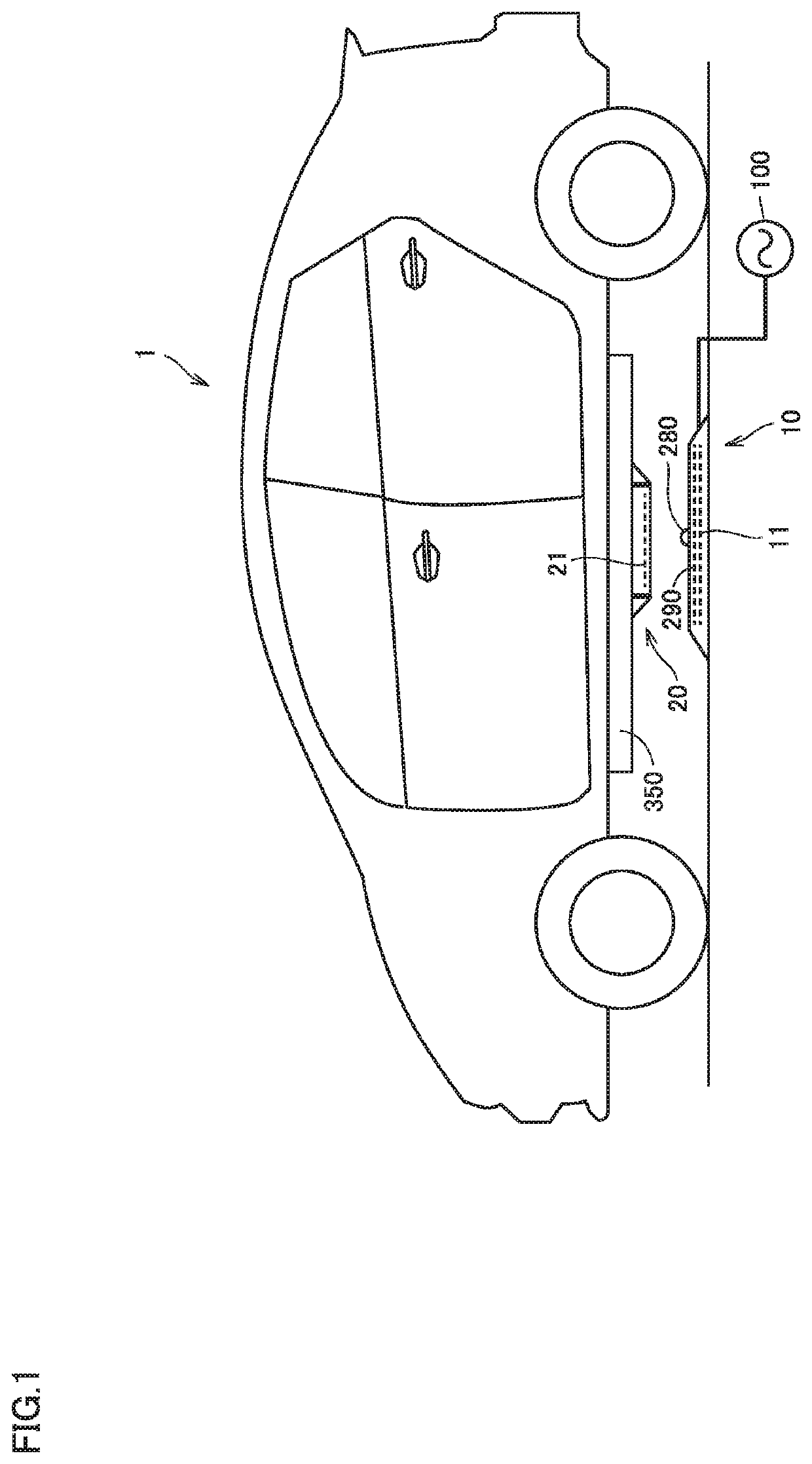
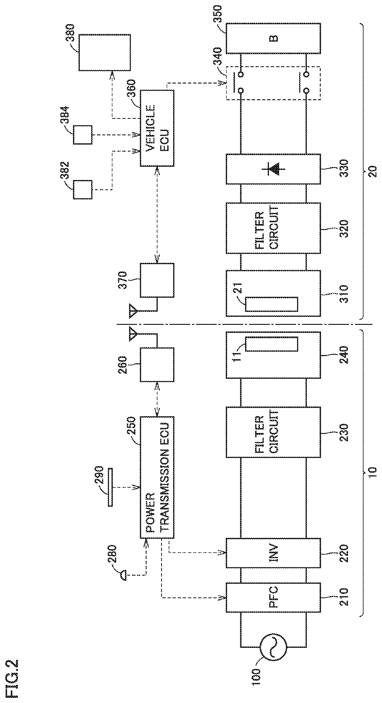
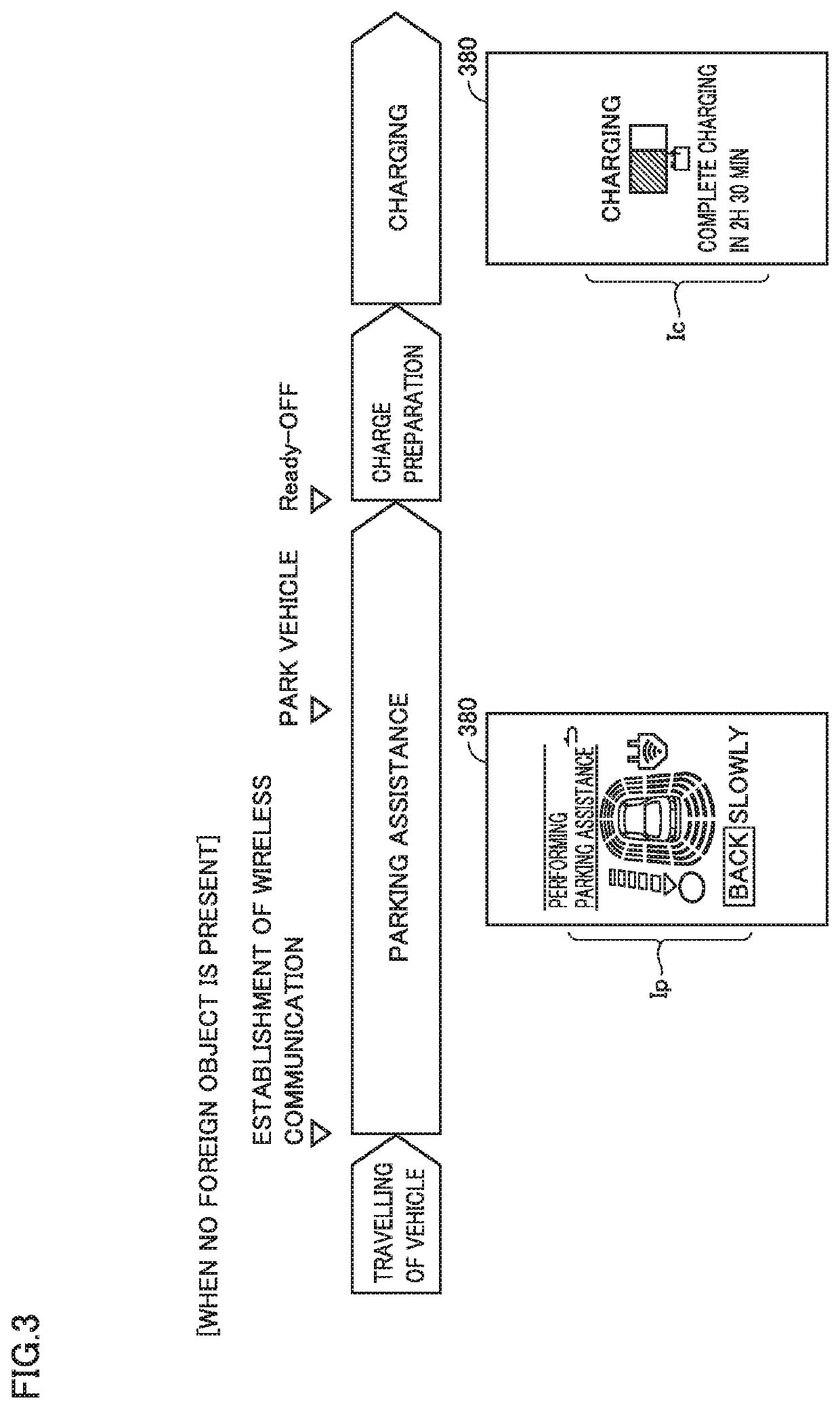
The notification system is applicable to a wireless power transfer system configured to transmit power in a wireless manner from a power transmission coil of a power transmission device provided in a parking space to a power reception coil mounted on a vehicle. The notification system includes a display device and a control device. When the distance between the power transmission device and the vehicle is less than a predetermined distance, a wireless communication is established between the power transmission device and the vehicle. After the wireless communication is established between the power transmission device and the vehicle, the control device performs a foreign object detection process to detect whether or not a foreign object is present above the power transmission coil. If a foreign object is detected by the foreign object detection process, the control device displays a foreign object detection image on a screen of the display device.

Description

CROSS REFERENCE TO RELATED APPLICATIONS[0001]This nonprovisional application claims priority to Japanese Patent Application No. 2018-208713 filed on Nov. 6, 2018 with the Japan Patent Office, the entire contents of which are hereby incorporated by reference.BACKGROUNDField[0002]The present disclosure relates to a notification system and a notification method applicable to a wireless power configured to transmit power in a wireless manner from a power transmission coil of a power transmission device provided in a parking space to a power reception coil mounted on a vehicle.Description of the Background Art[0003]Japanese Patent Laying-Open No. 2012-249400 discloses a system for charging a power storage device mounted on a vehicle by transmitting power in a wireless manner from a power transmission coil of a power transmission device provided in a parking space to a power reception coil mounted on the vehicle. This system includes a detection device configured to detect a foreign objec...

Claims


Application Information

Patent Timeline
Patent Type & Authority Applications(United States)
IPC IPC(8): H02J50/60H02J50/12H02J50/80H02J7/02B60L53/12B60L53/30
CPCH02J50/80H02J50/60H02J50/12B60L53/12B60L53/305B60Y2300/91H02J50/90B60Y2200/91H02J7/027H02J7/025B60L53/38B60L2250/16B60L2250/14B60L2240/80B60L2250/24B60L2240/12B60L53/124B60L53/66Y02T90/16Y02T10/70Y02T10/7072Y02T90/14Y02T90/12H02J7/0047H02J7/0013
Inventor NIWA, YAMATO
Owner TOYOTA JIDOSHA KK
Learn More