Multimode Heterogeneous IOT Networks

a heterogeneous iot network and multimode technology, applied in data switching networks, machine-to-machine/machine-type communication services, instruments, etc., can solve the problems of relatively high latency and intermediate bandwidth of cellular networks, and achieve the effect of maximizing signal to noise, and minimizing network induced nois

Inactive Publication Date: 2020-05-07
INNOVATION SCI LLC
View PDF14 Cites 18 Cited by
  • Summary
  • Abstract
  • Description
  • Claims
  • Application Information

AI Technical Summary

Benefits of technology

[0060]To minimize network induced noise, the novel IOT network may attempt to maintain distinct transmit / receive frequency bands or use time division for relatively physically closely spaced links of the network.
[0061]To minimize network induced noise and maximize signal to noise, the novel IOT network may calculate from locations of MDTUs and sensors, a direction of a transmitter to the corresponding intended receiver, and instruct the transmitting MDTU or sensor to configure antennae parameters to shape its transmit beam with high intensity propagating in the calculated direction.
[0062]To minimize network induced noise and maximize signal to noise, the novel IOT network may attempt to maintain distinct transmit / receive frequency bands or use time division, for relatively physically closely spaced links of the network.

Problems solved by technology

Cellular networks have intermediate bandwidth and relatively high latency.

Method used


Image

  • Multimode Heterogeneous IOT Networks
  • Multimode Heterogeneous IOT Networks
  • Multimode Heterogeneous IOT Networks

Examples


Embodiment Construction

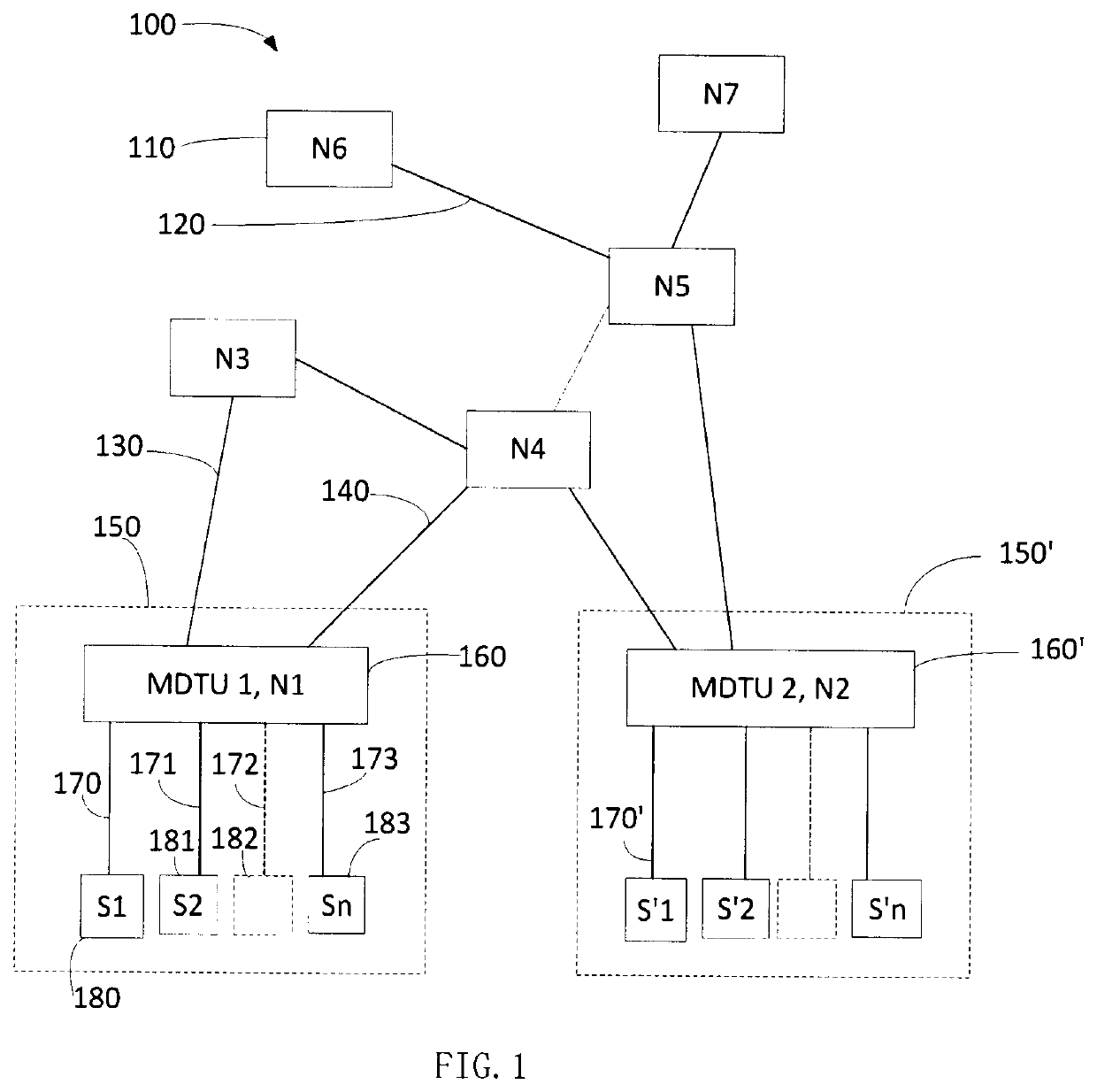
[0219]FIG. 1 shows novel IOT network 100. Network 100 is shown comprising nodes N1 to N7. Node 100, N6, is connected to Node 5, by link 120. Node N3 is connected to Node N1, that is element 1060, by link 130. Node N4 is connected to Node N1, by link 140. Element 160 is node N1, which is also an MDTU, identified as MDTU1. MDTU1 communicates with a plurality of sensors, S1, S2 to Sn (n representing an integer), numbered 180, 182, 183, and 183, by communication and / or control lines numbered 170, 171, 172, and 173. Communication and / or control line 172 and sensor 182 are shown in dashed lines indicating they may represent a plurality of sensors communicating data to node 160. FIG. 1 shows dashed box 150 representing are relatively localized region of space surrounding node 160 that contains sensors S1 to Sn, indicating that sensor data originating in the IOT network from sensors communicating with node 160 originates in the vicinity of node 160, for example within a 10 kilometers of nod...


PUM


Abstract

A novel IOT network, methods of making, structure and functions, and method of use are disclosed.

Description

1. CROSS REFERENCE TO RELATED APPLICATIONS[0001]The disclosure of U.S. Pat. No. 9,912,983, titled “Method and System for Efficient Communication,” which issued from application Ser. No. 15 / 626,192, and which names Teijun Wang and Tiehong Wang as inventors, is hereby incorporated herein by reference. U.S. provisional application 62 / 701,837, filed Jul. 22, 2018, naming Tiejun Wang, Beijing, CHINA; and Tiehong Wang, Plano, Tex. as applicants and inventors, is incorporated herein by reference.2. DEFINITIONS[0002]Sensor—A device which provides an output that varies with a physical property.Sensitivity—How much a sensor's output changes with a change of the physical property.Sampling rate—Number of sensor sample values for a physical property in a given period of time.Random error—Differences in repeated measurements of an presumably constant value for a physical quantity.Precision—Statistical variability of repeated measurements of a value of a physical property. Precision is limited by ...

Claims


Application Information

Patent Timeline
Patent Type & Authority Applications(United States)
IPC IPC(8): H04L29/08H04L12/24H04L12/707H04L12/735H04L9/06H04L9/08H04L45/128H04L45/24
CPCH04L41/0823H04L9/0643H04L45/128H04L45/24H04L41/0893H04L67/288H04L9/0869H04L67/2814G06T19/00H04L67/12H04W24/02H04W84/18H04W4/38H04W12/03H04W12/041H04L41/0895H04L41/0894H04L9/0894H04L9/3239H04L2209/805H04W4/70H04L67/34H04L63/123H04L63/126H04L12/4625H04W4/80H04L67/56H04L9/50H04L67/563H04L9/0866
Inventor WANG, TIEJUNWANG, TIEHONG
Owner INNOVATION SCI LLC
Why Eureka
Try Eureka