Autonomous driving device module mounting structure and autonomous driving electric vehicle

a technology for autonomous driving and electric vehicles, applied in electric propulsion mounting, battery/fuel cell control arrangement, transportation and packaging, etc., can solve the problems of troublesome connection of wiring or devices, impaired convenience of vehicles, and inability to maintain the vehicle, so as to increase the heat dissipation amount from the inner casing portion to the cooling air blown out from the air blowing uni

Active Publication Date: 2020-05-14
TOYOTA JIDOSHA KK
View PDF4 Cites 3 Cited by
  • Summary
  • Abstract
  • Description
  • Claims
  • Application Information

AI Technical Summary

Benefits of technology

[0031]According to the above aspect, the inner casing portion may be provided with the heat dissipation portion that protrudes toward the flow passage of the cooling air blown out from the air blowing unit and the surface area of the inner casing, portion on the flow passage side in the inner casing portion can be increased. For this reason, the heat dissipation amount from the inner casing portion to the cooling air blown out from the air blowing unit can be increased. Further, since the heat dissipation portion may extend along the flow passage of the cooling air blown out from the air blowing unit, it is possible to prevent the heat dissipation portion from serving as a resistance against the cooling air.

Problems solved by technology

However, when the space that can be freely used by the passenger is decreased in size, the convenience of the vehicle is impaired.
Meanwhile, when an opening portion for connecting a wiring or device is provided at both sides in the front to rear direction of the vehicle of the peripheral wall portion of the outer casing portion, it is troublesome to connect a wiring or device to the map information storage unit, the own position estimation unit, and the driver state estimation unit.

Method used


Image

  • Autonomous driving device module mounting structure and autonomous driving electric vehicle
  • Autonomous driving device module mounting structure and autonomous driving electric vehicle
  • Autonomous driving device module mounting structure and autonomous driving electric vehicle

Examples


Embodiment Construction

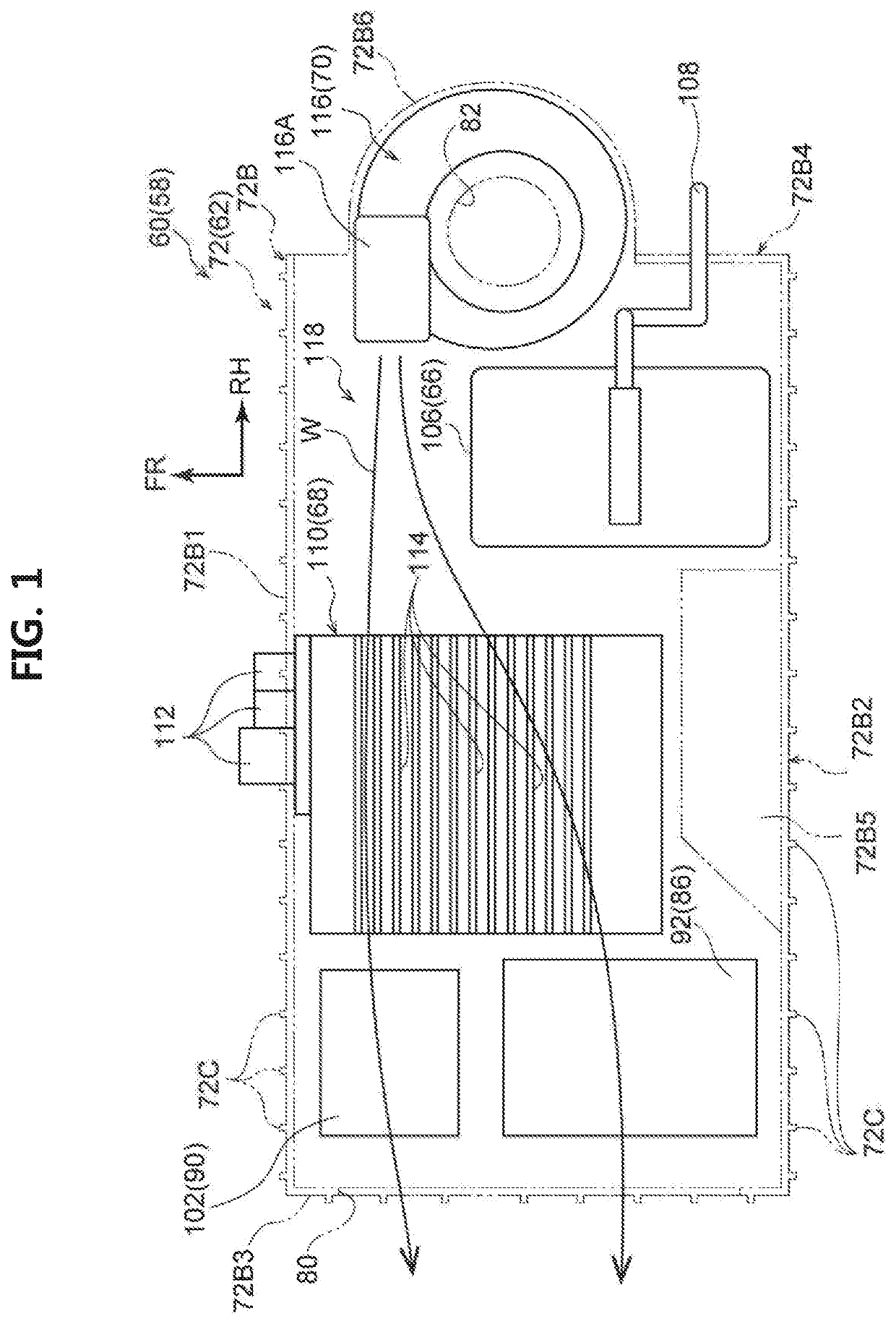
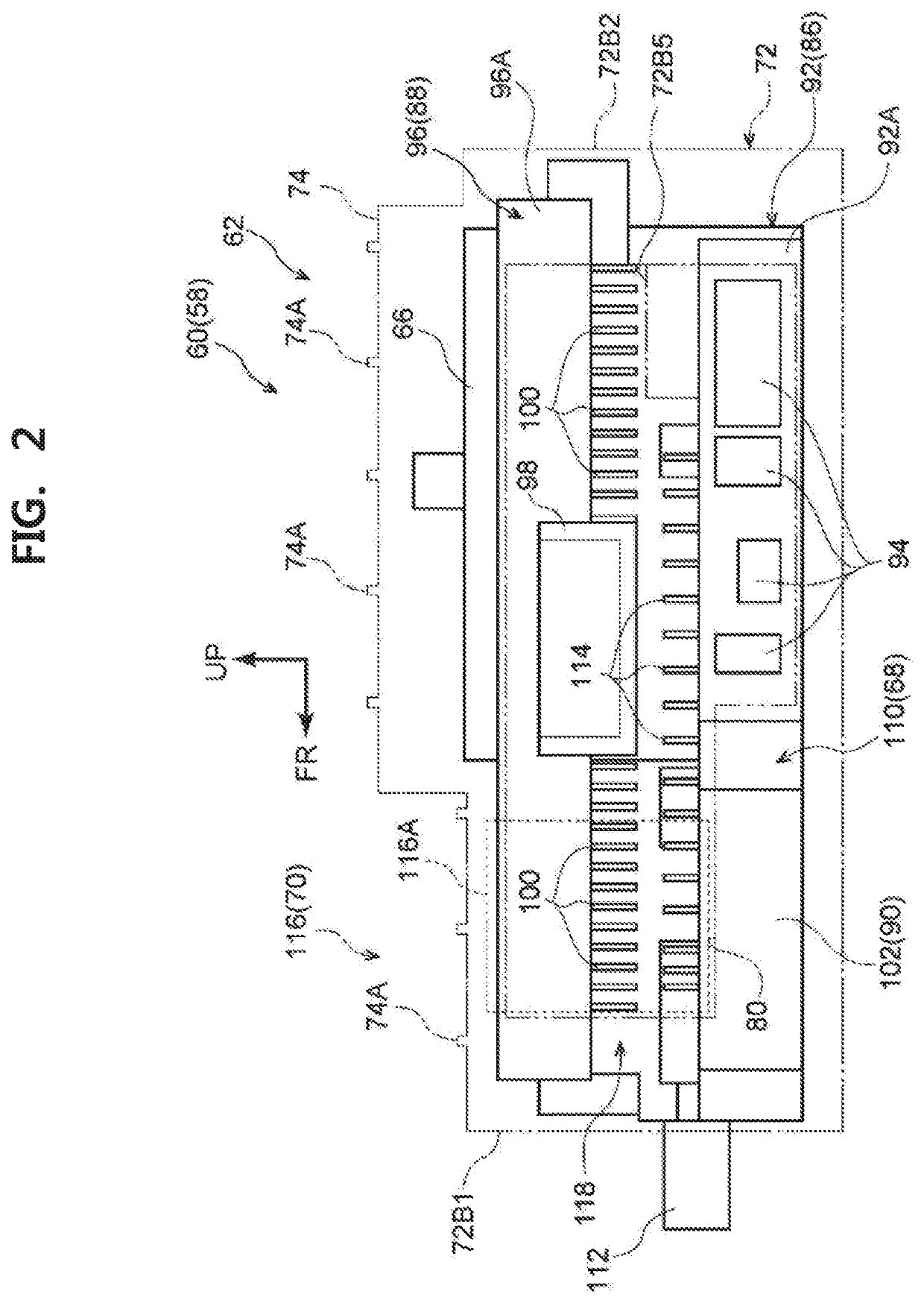
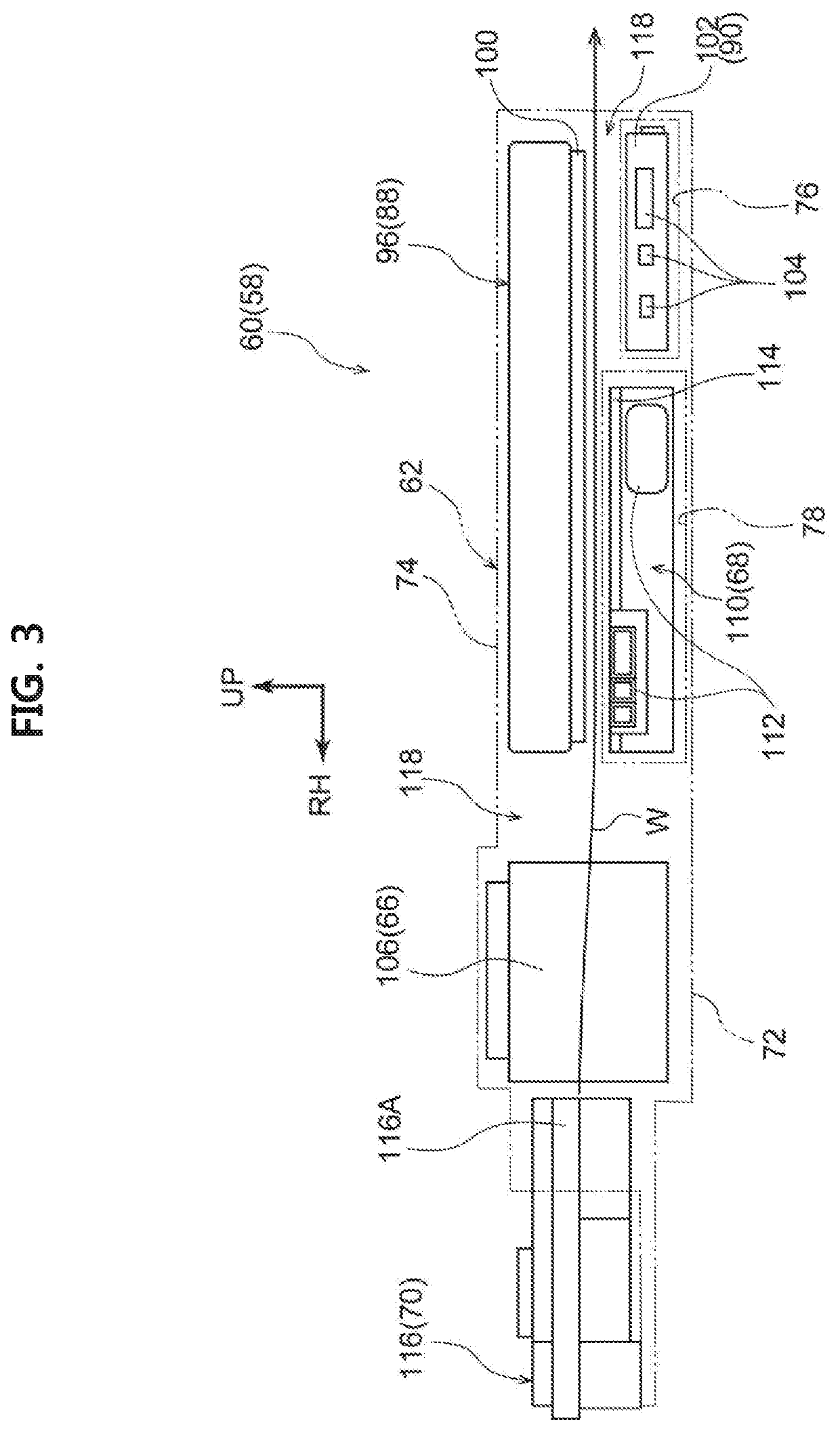
[0048]Hereinafter, an example of an embodiment of an autonomous driving device module mounting structure will be described with reference to FIGS. 1 to 6. Furthermore, in the drawings, an arrow FR indicates a vehicle front side, an arrow UP indicates a vehicle upper side, and an arrow RH indicates a right side of the width direction of the vehicle.

[0049]Above all, an overall configuration of a “vehicle 10” which corresponds to an autonomous driving electric vehicle and an own vehicle adopting an autonomous driving device module mounting structure according to the embodiment will be described with reference to FIGS. 5 and 6.

[0050]As illustrated in FIG. 6, a vehicle body front part 14 which constitutes a part on a vehicle front side of a vehicle body 12 of a vehicle 10 includes a pair of front side members 16, a bumper reinforcement 18 (hereinafter, referred to as a bumper R / F 18), and a dash panel 20.

[0051]The front side member 16 includes a front portion 16A which extends in the fro...


PUM


Abstract

An autonomous driving device module mounting structure includes: a floor panel that constitutes a part of a vehicle body and extends in a front to rear direction of a vehicle and a width direction of the vehicle: a rear seat that is disposed on a vehicle upper side of the floor panel such that a gap is formed with respect to the floor panel; and an autonomous driving device module that is equipped with a plurality of devices and is disposed on the vehicle upper side of the floor panel and a vehicle lower side of the rear seat.

Description

CROSS REFERENCE TO RELATED APPLICATIONS[0001]This application claims priority to Japanese Patent Application No. 2018-212533 filed on Nov. 12, 2018, which is incorporated herein by reference in its entirety including the specification, drawings and abstract.BACKGROUND1. Technical Field[0002]This disclosure relates to an autonomous driving device module mounting structure and an autonomous driving electric vehicle.2. Description of Related Art[0003]Published Japanese Translation of PCI application No. 2018-511515 (JP-A-2018-511515) below discloses a disclosure related to a driving support system for a vehicle. In this driving support system for the vehicle, the vehicle can be switched from a manual driving mode to an autonomous driving mode by an autonomous driving device.SUMMARY[0004]Incidentally, in order to install the autonomous driving device in the vehicle, a space for disposing devices constituting the autonomous driving device needs to be secured. Then, as a space that can be...

Claims


Application Information

Patent Timeline
Patent Type & Authority Applications(United States)
IPC IPC(8): B60R16/023B60R16/03B60H1/32B60H1/24B60W40/08
CPCB60H1/246B60R16/03B60H1/32B60R16/0231B60W40/08B62D25/20B60L1/00B60K1/04B60N2/002B60N2/005B60L58/26B60K2001/005B60R16/033B60R16/0239B60H2001/003B60K31/00B60W30/14H05K7/20909H05K7/20145B60W2040/0881
Inventor TAKEI, KENTA
Owner TOYOTA JIDOSHA KK
Why Eureka
Try Eureka