Autonomous thrust vectoring ring wing pod

a technology of ring wing pod and wing pod, which is applied in the direction of propellers, vertical landing/take-off aircraft, transportation and packaging, etc., can solve the problems of limited range of operation, heavy actuators, and inability to fully control the flight capability of aircraft, and achieve the effect of superior aircraft attitude control

Active Publication Date: 2020-05-14
TEXTRON INNOVATIONS
View PDF0 Cites 10 Cited by
  • Summary
  • Abstract
  • Description
  • Claims
  • Application Information

AI Technical Summary

Benefits of technology

[0004]The present disclosure teaches technical advantages as an autonomous thrust vectoring ring wing pod. Thrust vectoring is the ability of a vehicle, such as an aircraft, to manipulate the direction of the thrust from its propellers, engines, or motors, to control the attitude or angular velocity of the vehicle. A plurality of distributed propulsion element (thruster) layout within a self-articulating ring wing pod allows the pod to selectively control its thrust vector by controlling each propulsion element in the pod. This unique feature allows autonomous and independent control of the tilting ring wing relative to the aircraft. The ring wing pod acts as both a nacelle to house the propulsion elements as well as a lifting surface when in wing-borne flight. The autonomous thrust vectoring ring wing pod also provides superior aircraft attitude control in wing-borne flight, thus negating the need for conventional surface controls.
[0007]Each of the ring wing pods can include a plurality of rotors that can be selectively controlled to articulate the thrust pod to a desired orientation. Once in the desired position, the rotors are further configured to create propulsion for the aircraft. The self-articulating thrust pod disclosed is better situated to quickly articulate positions, and has a greater bandwidth than actuators traditionally used to articulate aircraft thrusters. Further, the disclosure reduces redundancy, as the rotors used to provide thrust for the aircraft are also the rotors used to articulate the orientation of the thrust pod, rather than having an entirely different assembly such as an actuator for articulating the thrust pod.

Problems solved by technology

These systems, though robust, have inherent disadvantages in weight and bandwidth.
The actuators can be heavy limiting the flight capabilities of the aircraft and inefficient in adjusting the orientation of the thrusters in response to real-time conditions, with a limited range of operation.
Vanes can be introduced to generally direct thrust, but come at an added complexity and cost to the aircraft.
Vanes are also heavy, further limiting the capabilities of the aircraft.
Further, the thrust angles are limited to the orientation and number of vanes provided.

Method used


Image

  • Autonomous thrust vectoring ring wing pod
  • Autonomous thrust vectoring ring wing pod
  • Autonomous thrust vectoring ring wing pod

Examples


Embodiment Construction

[0016]The preferred version of the inventions presented in the following written description and the various features and advantageous details thereof are explained more fully with reference to the non-limiting examples included in the accompanying drawings and as detailed in the description which follows. Descriptions of well-known components are omitted so as to not unnecessarily obscure the principle features of the invention as described herein. The examples used in the following description are intended to facilitate an understanding of the ways in which the invention can be practiced and to further enable those skilled in the art to practice the invention. Accordingly, these examples should not be construed as limiting the scope of the claimed invention.

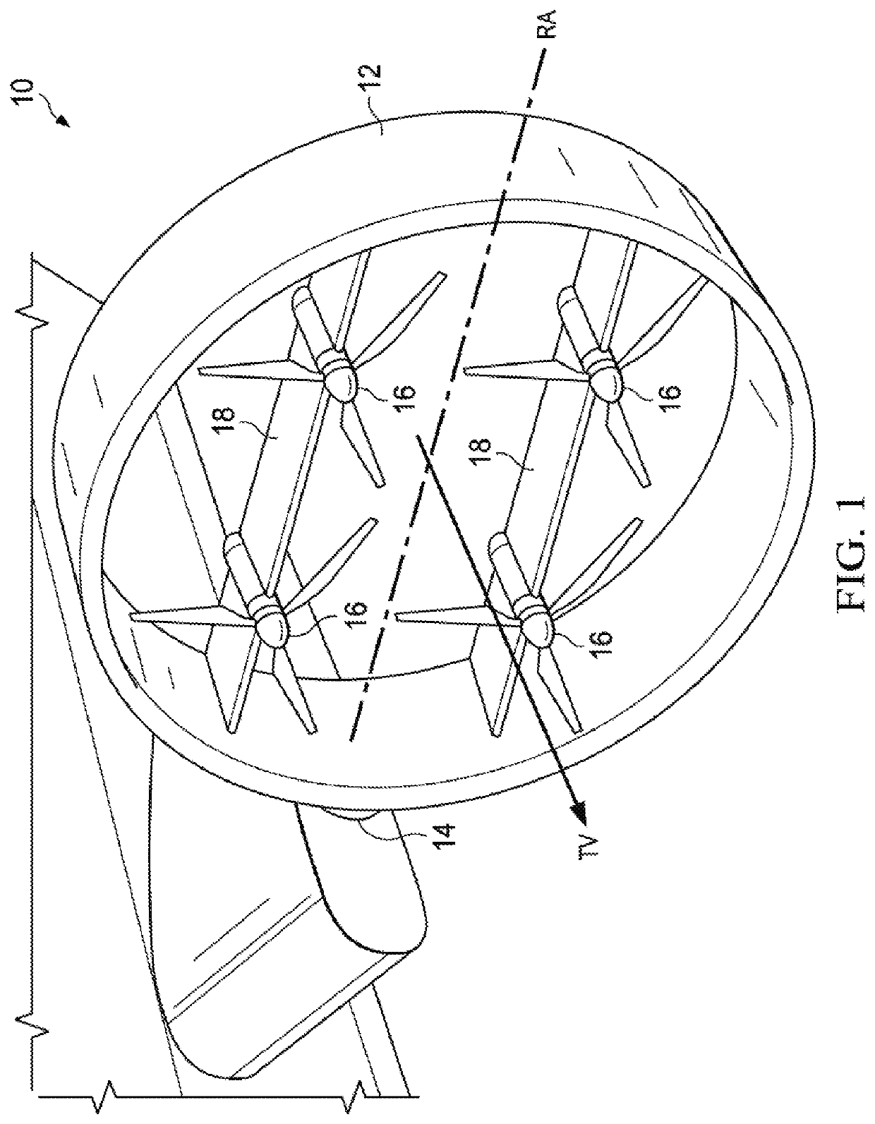
[0017]FIG. 1 is a perspective view of a ring wing pod, designated generally as 10, in accordance with an embodiment of the present disclosure. A ring wing pod 10 can include a duct 12. The duct 12 is preferably a rigid material...


PUM


Abstract

An autonomous thrust vectoring ring wing pod is disclosed. A plurality of distributed propulsion element (thruster) layout within a self-articulating ring wing pod allows the pod to selectively control its thrust vector by controlling each propulsion element in the pod. This arrangement allows autonomous and independent control of the tilting of the ring wing relative to the aircraft. The ring wing pod acts as both a nacelle to house the propulsion elements as well as a lifting surface when in wing-borne flight. The autonomous thrust vectoring ring wing pod also provides superior aircraft attitude control in wing-borne flight, thus negating the need for conventional surface controls.

Description

BACKGROUND1. Field of the Invention[0001]The present invention is generally related to tiltrotor aircraft, and specifically to tiltrotor thrusters that articulate orientation without the use of an actuator.2. Background of the Invention and Description of Related Art[0002]Traditional tiltrotor aircraft are utilized in situations in which vertical take-off and landing of the aircraft is desired. The thrusters of such aircraft are oriented vertically to provide vertical lift. Once in the air, the thrusters of the aircraft articulate from a vertical to a horizontal position via an actuator to facilitate forward flight. Traditionally, aircraft with tilting rotors, ducted fans, or thrusting elements have utilized nacelle actuators in order change the angle of the thrust element relative to the wing / airframe. These systems, though robust, have inherent disadvantages in weight and bandwidth. The actuators can be heavy limiting the flight capabilities of the aircraft and inefficient in adju...

Claims


Application Information

Patent Timeline
Patent Type & Authority Applications(United States)
IPC IPC(8): B64C39/06B64C27/28B64C27/08B64C27/20B64C39/00B64C39/02
CPCB64C39/005B64C27/28B64C27/08B64C39/06B64C2201/042B64C2201/108B64C39/024B64C2201/162B64C27/20B64U50/19B64U30/20B64U50/14B64C29/0033B64C11/46B64C11/001B64U10/20B64U30/297
Inventor MORRIS, KEVINBRODEUR, NICHOLASFENNY, CARLOS
Owner TEXTRON INNOVATIONS
Why Eureka
Try Eureka