Lockout system for energy sources

a technology for energy sources and locks, applied in the field of industrial safety devices, can solve the problems of confusion and disorganization of the general appearance of lockout/tagout equipment, unwieldy and inconvenient use of prior-art kits, and inconvenient us

Active Publication Date: 2020-05-14
ACCUFORM MFG +1
View PDF0 Cites 4 Cited by
  • Summary
  • Abstract
  • Description
  • Claims
  • Application Information

AI Technical Summary

Benefits of technology

[0028]Another aspect of the present invention is directed to a method of locking an energy source comprising the steps of providing a hasp assembly defining a plurality of tag slots each defining a lock opening, where the hasp assembly has an openable hasp and a locking bar operable with the openable hasp by moving between a locked position and an unlocked position, the locking bar defining a plurality of notches configured to align with respective ones of the plurality of tag slots when the locking bar is in the locked position; providing a plurality of tags each defining a tag opening and configured to be removably installed in one of the tag slots with a first end portion of the tag sized to be received in one of the notches and the tag opening aligned over a lock opening; moving the locking bar to the unlocked position, thereby opening the openable hasp; installing

Problems solved by technology

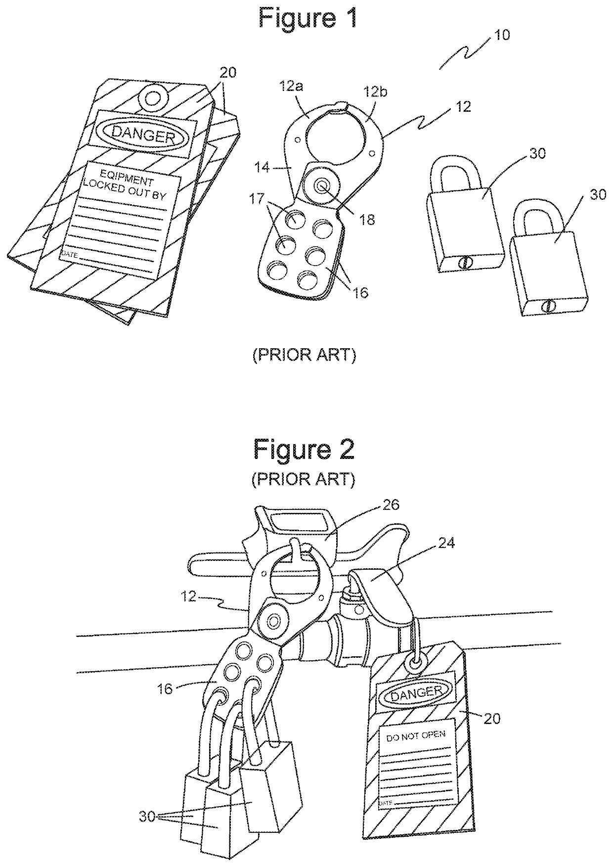
However, these prior-art kits become unwieldy and inconvenient to use especially when multiple workers have locked a machine.
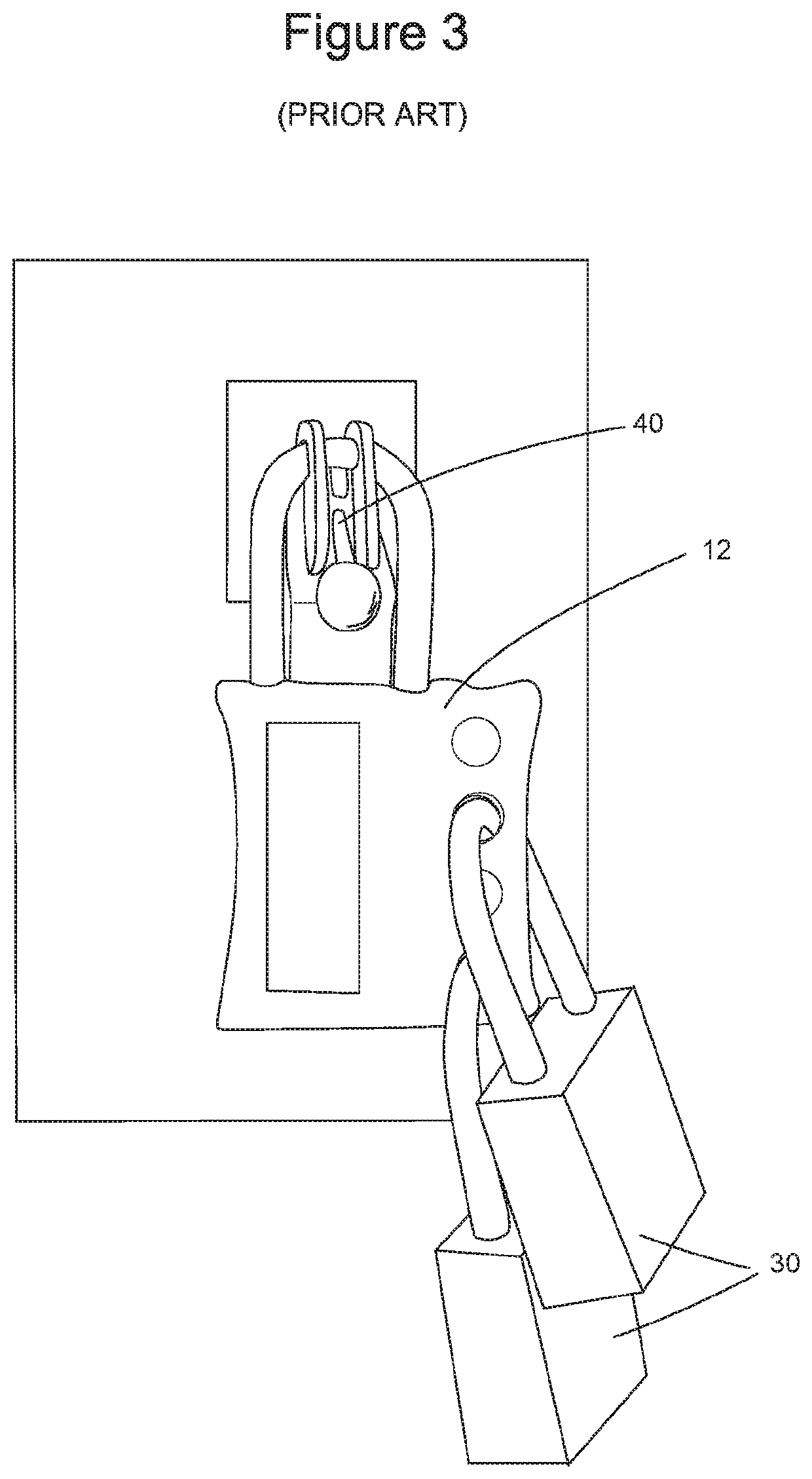
When many workers install locks and tags on a hasp to lock out a piece of equipment, the access to the hasp is restricted and the general appearance of the lockout/tagout equipment is confusing and disorganized.
The jumble of locks and tags is inconvenient to use, sometimes deterring workers from complying with lockout procedures.
Also, it can be difficult to identify all of the workers who have

Method used


Image

  • Lockout system for energy sources
  • Lockout system for energy sources
  • Lockout system for energy sources

Examples


Embodiment Construction

[0045]FIG. 15 illustrates a further embodiment of a lockout system of the present invention showing an alternative hasp assembly with slots for tags on the front and back of the system.

[0046]FIG. 15a illustrates an embodiment of a lockout system with slots for tags on the front and back of the system, in a closed position with tags, requiring at least one padlock to remain in a locked position.

[0047]FIG. 15b illustrates an embodiment of a lockout system of the present invention, with slots for tags on the left and right, requiring at least one padlock to remain in a locked position.

[0048]FIG. 15c illustrates an embodiment of a lockout system of the present invention in an open position, having a reduced device area, with slots for tags on the left, requiring at least one padlock to remain in a locked position.

[0049]FIG. 16 illustrates the lockout system of FIG. 15 in an open position showing multiple tag locations along the front and back.

[0050]FIG. 17 illustrates another embodiment...


PUM


Abstract

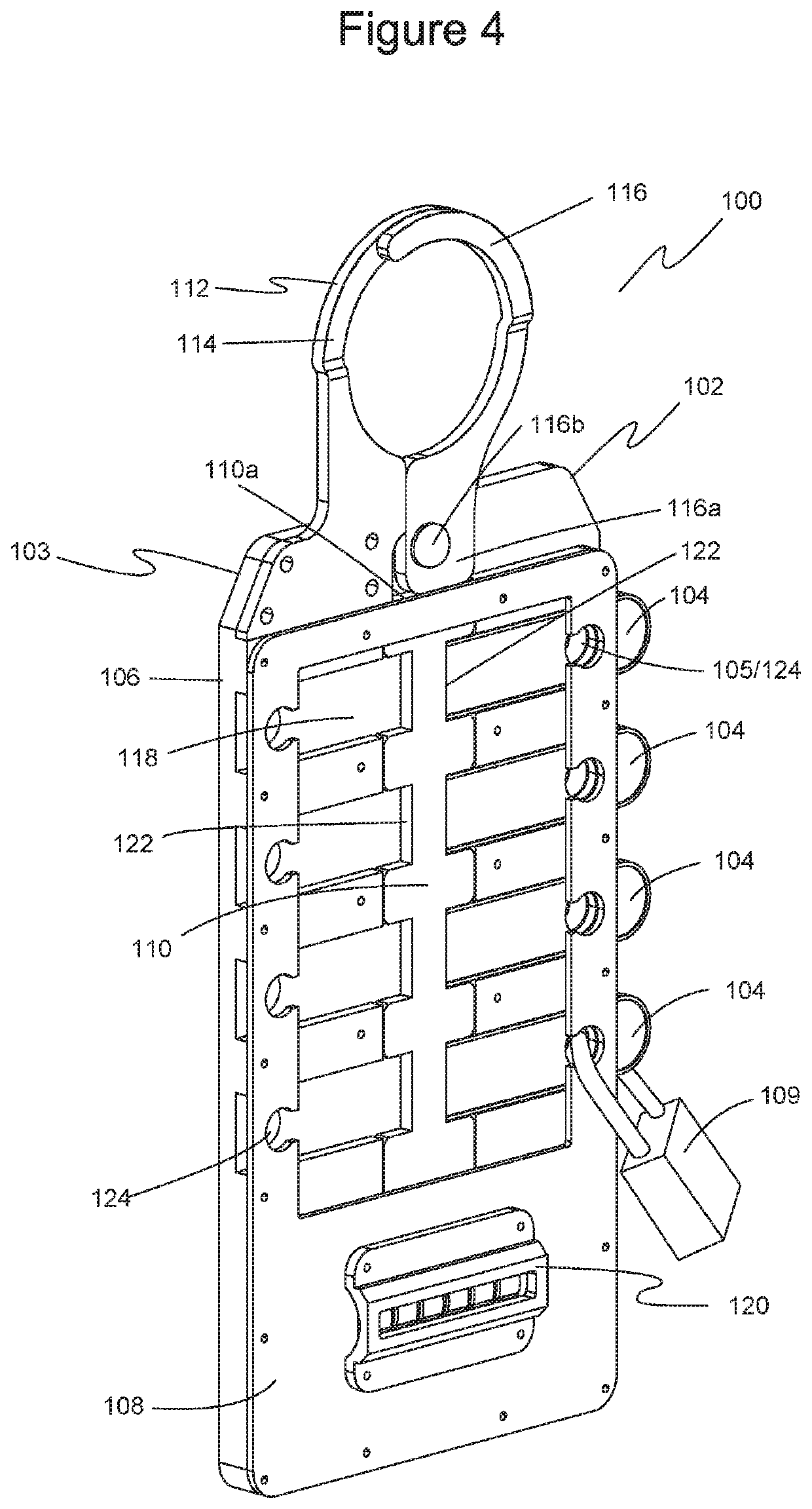
A lockout system includes a hasp assembly and a plurality of tags. The hasp assembly has a back plate defining slots each sized and shaped to receive a tag. The back plate and tags each have openings that align when a tag is received in a slot. A first hasp portion has a first loop portion and a second hasp portion has a second loop portion. The first and second hasp portions are rotatable with respect to one another such that moving the lockout system has both an unlocked position and a locked position associated with an open position and a closed position. In the closed position, the first and second hasp portions complete and define a closed loop, where one or more tags can be installed in slots preventing further movement from the closed position.

Description

[0001]This application is a continuation-in-part of Ser. No. 15 / 785,582, filed on Oct. 17, 2017, which is a continuation of nonprovisional application Ser. No. 15 / 435,365, filed on Feb. 17, 2017, which issued on Jan. 30, 2018 as U.S. Pat. No. 9,881,749, which claims priority to provisional application No. 62 / 296,910, filed on Feb. 18, 2016.BACKGROUND OF THE INVENTION1. Field of the Invention[0002]The present invention relates generally to industrial safety devices. More particularly, the present invention relates to a lockout system and apparatus for use with industrial equipment and energy sources.2. Description of the Prior Art[0003]Energy sources in machines and equipment is a hazard to workers. Energy sources include electrical, mechanical, hydraulic, pneumatic, chemical, and thermal energy sources. Workers servicing or maintaining machines or equipment must properly control energy sources to avoid accidents. While servicing and maintaining machines and equipment, for example, a...

Claims


Application Information

Patent Timeline
IPC IPC(8): E05B51/00H01H9/28E05B63/14E05B67/38E05B17/22E05B65/48E05B65/00E05B63/12E05B63/00E05B43/00E05B39/04E05B37/00G07C9/00E05B41/00
CPCE05B63/143G07C2009/00769E05B41/00H01H9/281E05B2047/0094E05B63/0004G07C9/00896H01H9/283E05B63/0052G07C9/00309E05B51/00E05B39/04E05B67/32E05B2047/0071E05B65/48E05B65/006E05B37/0096E05B63/123E05B2047/0067E05B67/38E05B63/0069E05B43/005E05B17/226E05B65/0089E05B67/383G07C9/0069
Inventor GRIFFIN, JASON P.SHANK, ROBERT
Owner ACCUFORM MFG
Why Eureka
Try Eureka