Intermediate adapter connector and connector assembly

a technology of adapter connector and connector assembly, which is applied in the direction of electrical apparatus, connection, coupling device connection, etc., can solve the problems of not meeting the requirements of use, and achieve the effects of convenient manufacture, improved protection of signal interference, and simplified combine structur

Active Publication Date: 2020-05-14
MOLEX INC
View PDF2 Cites 4 Cited by
  • Summary
  • Abstract
  • Description
  • Claims
  • Application Information

AI Technical Summary

Benefits of technology

[0034]The present disclosure at least has the following effects: in the intermediate adapter connector, by that a plurality of insulating spacers and a plurality of terminal modules are alternately stacked to form a main structure, and the shielding plate of each terminal module can cover a very large part of the plurality of conductive terminals (including a portion of the first contact portion and a portion of the second contact portion), and thus can provide comprehensive shielding between the conductive terminals f the adjacent terminal modules, which can shield the signal interference more effectively.
[0035]In addition, there are insulating spacers having the same configurations but provided at different directions in the plurality of insulating spacers, and there are terminal modules having the same configurations but provided at different directions in the plurality of terminal module, and the overall combine structure is simplified in the structure in which the number of terminals arranged varies, which is not only convenient to manufacture to reduce manufacturing cost, but also has more flexible expansion performance. Moreover, the first mating port and second mating port of the intermediate adapter connector have the same configurations, and are capable of connecting the first connector and the second connector which have the same configurations.

Problems solved by technology

The above connector is provided on the circuit board or directly connects the two circuit boards, however, if the above connector acts as an intermediate adapter connector that connects the two connectors, for example the intermediate adapter connector is used to connect the connectors respectively provided on two circuit boards to increase the distance between the two circuit boards, it can not meet the requirement of use.

Method used


Image

  • Intermediate adapter connector and connector assembly
  • Intermediate adapter connector and connector assembly
  • Intermediate adapter connector and connector assembly

Examples


Embodiment Construction

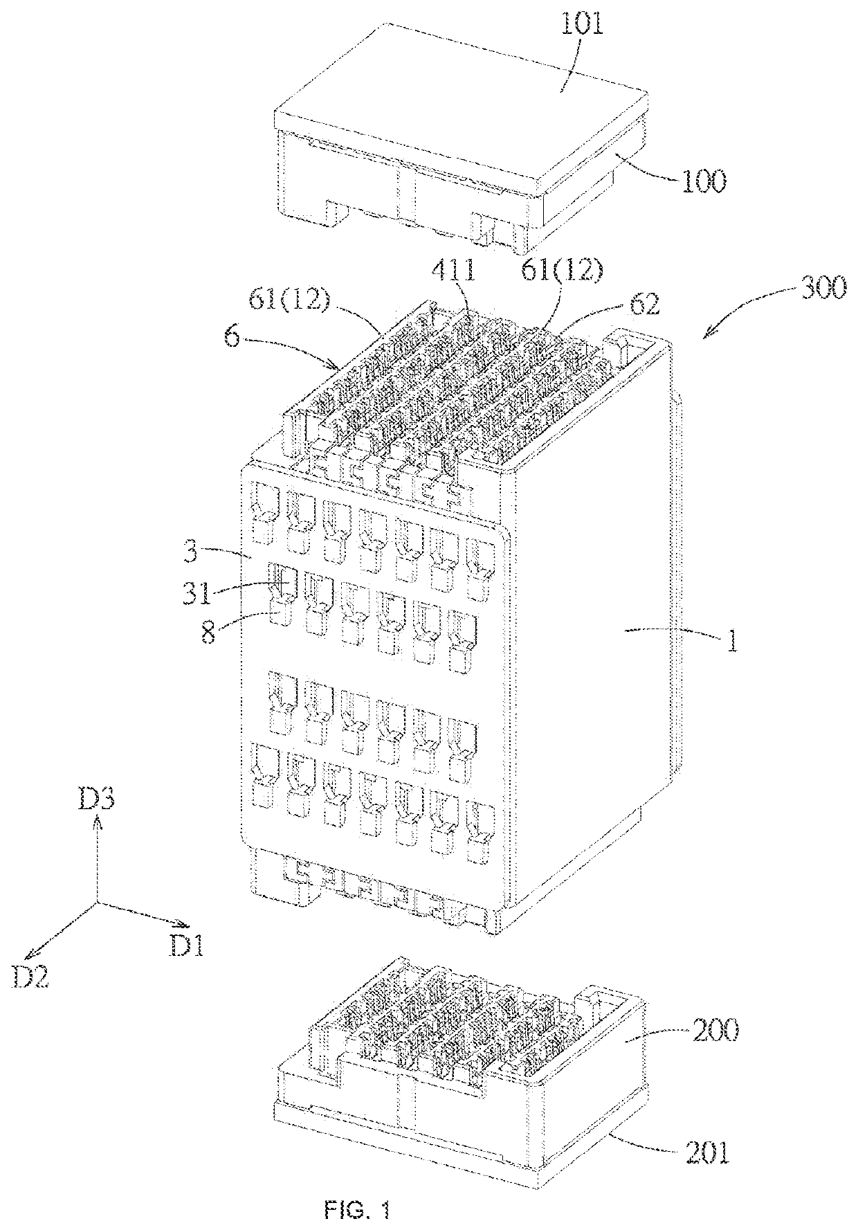
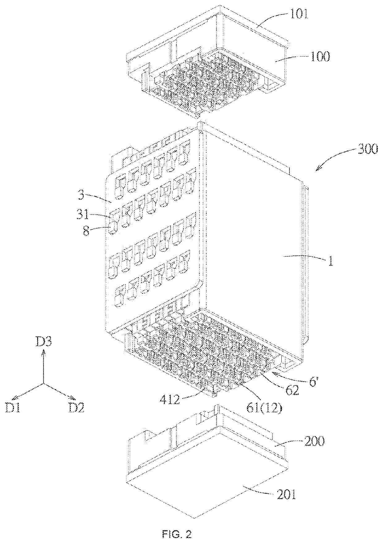
[0113]Referring to FIG. 1 and FIG. 2, an embodiment of an electrical connector assembly of the present disclosure comprises a first connector 100, a second connector 200, and an intermediate adapter connector 300. The first connector 100 is configured to mount on a first circuit board 101. The second connector 200 is configured to mount on a second circuit board 201. The intermediate adapter connector 300 is configured to mate with the first connector 100 and the second connector 200 so as to electrically connect the first connector 100 and the second connector 200, and the intermediate adapter connector 300 has a first mating port 6 configured to mate with the first connector 100 and a second mating port 6′ configured to mate with the second connector 200. In the embodiment, the first connector 100 and the second connector 200 have the same overall configurations and are capable of mating with each other face-to-face, for example, the first connector 100 and the second connector 20...


PUM


Abstract

The present disclosure discloses an intermediate adapter connector and an electrical connector assembly, which are adapted to electrically connect a first connector and a second connector. The intermediate adapter connector comprises a plurality of insulating spacers and a plurality of terminal modules, the plurality of terminal module and the plurality of insulating spacer are alternately arranged and stacked in a first direction, so that each terminal module is positioned between two adjacent insulating spacers, and each terminal module comprises a terminal plate and a shield plate which are stacked in a front-rear direction, the terminal plate has a plurality of conductive terminals arranged in a second direction, each conductive terminal has a first contact portion and a second contact portion positioned at two opposite sides in a third direction.

Description

FIELD OF THE PRESENT DISCLOSURE[0001]The present disclosure relates to an electrical connector, and particularly relates to an intermediate adapter connector and an electrical connector assembly.BACKGROUND OF THE PRESENT DISCLOSURE[0002]U.S. Pat. No. 5,702,258 discloses a connector illustrating a plurality of shield members, each shield member electrically connects at least two points to a selected contact assembly. U.S. Pat. No. 7,798,852 discloses a connector in which FIG. 23D illustrates that two terminal columns are arranged such that the wide ground shield terminal faces a pair of narrow signal terminals. The terminal pattern is maintained in a straight line. Each pair of signal terminals has a ground terminal on a side of the signal terminals pair and at least one ground terminal faces the signal terminal pair. The shield arrangement between the ground terminals and the signal terminal pairs is only between the body portions of the terminals, but is not between the contact por...

Claims


Application Information

Patent Timeline
Patent Type & Authority Applications(United States)
IPC IPC(8): H01R12/70H01R13/6587H01R12/72
CPCH01R12/727H01R13/6587H01R12/7082H01R13/502H01R13/6581H01R31/06H01R12/73H01R13/514H01R13/6471H01R13/6586
Inventor GOH, HOON-CHANWONG, CHIE-MENG
Owner MOLEX INC
Why Eureka
Try Eureka