Magnetic filtration apparatus

a filtration apparatus and magnetic technology, applied in the direction of filtration separation, liquid displacement, separation process, etc., can solve the problems of metal particles generated, metal parts surface wear out, contaminating the liquid circulating inside the device and equipment, etc., to achieve simple structure, improve liquid quality, and simple

Active Publication Date: 2020-05-21
MAEDA SHELL SERVICES CO LTD
View PDF0 Cites 10 Cited by
  • Summary
  • Abstract
  • Description
  • Claims
  • Application Information

AI Technical Summary

Benefits of technology

[0024]In addition, in the invention, the outer surface of the treatment container preferably has at least one projection which locks the magnet case attached around the outer surface of the treatment container, thereby positioning the magnet case and preventing the magnet case from moving downwardly.
[0025]As described above, in the magnetic filtration apparatus according to the present invention, the magnetism effect by the magnetic means installed in the outside of the treatment container for magnetic separation permits the magnetic substances contaminating the liquid flowing through the treatment container to be attracted to the inner wall of the treatment container, and separated and removed from the liquid. On the other hand, the magnetic substances which have been separated and removed from the liquid, and captured on the inner wall of the treatment container, are allowed to fall into the lower portion of the treatment container due to the gravity, or their own weight, by the cancellation of the effect of the magnetic field generated by the magnetic means.
[0026]The treatment container is connected with the detachable collecting container positioned below the treatment container, via the communication passage. Thus, opening the valve installed on the communication passage permits the magnetic substances, which are allowed to fall into and congregate in the lower portion of the treatment container, to automatically flow into the collecting container due to the gravity, namely, their own weight. If the communication passage is blocked by closing the valve at a stage when a predetermined amount of the magnetic substances is accommodated in the collecting container, the magnetic substances collected in the collecting container are easily discharged to the outside of the collecting container by detaching the collecting container. The discharge of the magnetic substances can be simply and easily performed without simultaneously discharging the liquid in the treatment container, thereby resolving the problem of the treatment of the liquid which is discharged simultaneously with the magnetic substances.
[0027]Moreover, the above-mentioned magnetic filtration apparatus according to the invention comprises the treatment container for magnetic separation, the collecting container positioned below the treatment container, the communication passage for communicating the treatment container and the collecting container, and the valve installed on the communication passage. By opening the valve, the captured magnetic substances are allowed to flow from the treatment container into the collecting container due to their own weight. Thus, the magnetic filtration apparatus has a simple structure as an apparatus, and also permits a successful discharge of the captured magnetic substances from the treatment container, thereby advantageously avoiding the problem that the captured magnetic substances contaminate the liquid in the treatment container again to deteriorate the quality of the liquid.

Problems solved by technology

During use of those devices and equipment, surfaces of their metal parts are gradually worn out to generate metal particulates, and the metal particulates generated due to the abrasion of the metal parts inevitably contaminate the liquid circulating inside the devices and equipment, and become suspended in the liquid.
Metal particles generated from the ground workpiece, such as fine metal powder, metal abrasive grains and waste metal (cuttings), contaminate the coolant to be recovered from the processing part.
It is difficult to reuse the coolant contaminated with the metal particles.
Thus, the used lubricating oil, hydraulic oil, coolant and the like are contaminated with particulates of the ferromagnetic substances.
Furthermore, the ferromagnetic particulates are firmly attached to the pole pieces, thereby rendering the removal operation of the ferromagnetic particulates time-consuming and troublesome, and thus resulting in a significant trouble in its workability.
However, the above-mentioned type of magnetic filtration apparatus necessarily has a relatively complicated structure for discharging the ferromagnetic particulates out of the flow passage, since the ferromagnetic particulates captured by the magnet arranged in the outside of the flow passage exist within the flow passage, and a discharging passage is required to be installed independently of the flow passage through which the liquid is allowed to flow.
In addition, an amount of use of the liquid for sufficiently flowing out the ferromagnetic particulates captured inside the passage tends to be increased, thereby causing a rather significant trouble in treatment of the liquid discharged together with the ferromagnetic particulates.
In the case where the discharge of the captured ferromagnetic particulates is insufficient, the liquid after the magnetic separation, which is to flow out from the magnetic filtration apparatus, is contaminated with the ferromagnetic particulates existing in the flow passage, resulting in problems including deterioration of efficiency of purification or filtration of the liquid.
Thus, the magnetic filtration apparatus mentioned above is not yet satisfactory in terms of workability of washing or cleaning operation.

Method used


Image

  • Magnetic filtration apparatus
  • Magnetic filtration apparatus
  • Magnetic filtration apparatus

Examples


Embodiment Construction

[0038]To further clarify the structure of the present invention, embodiments of the present invention will be described in detail by reference to the drawings.

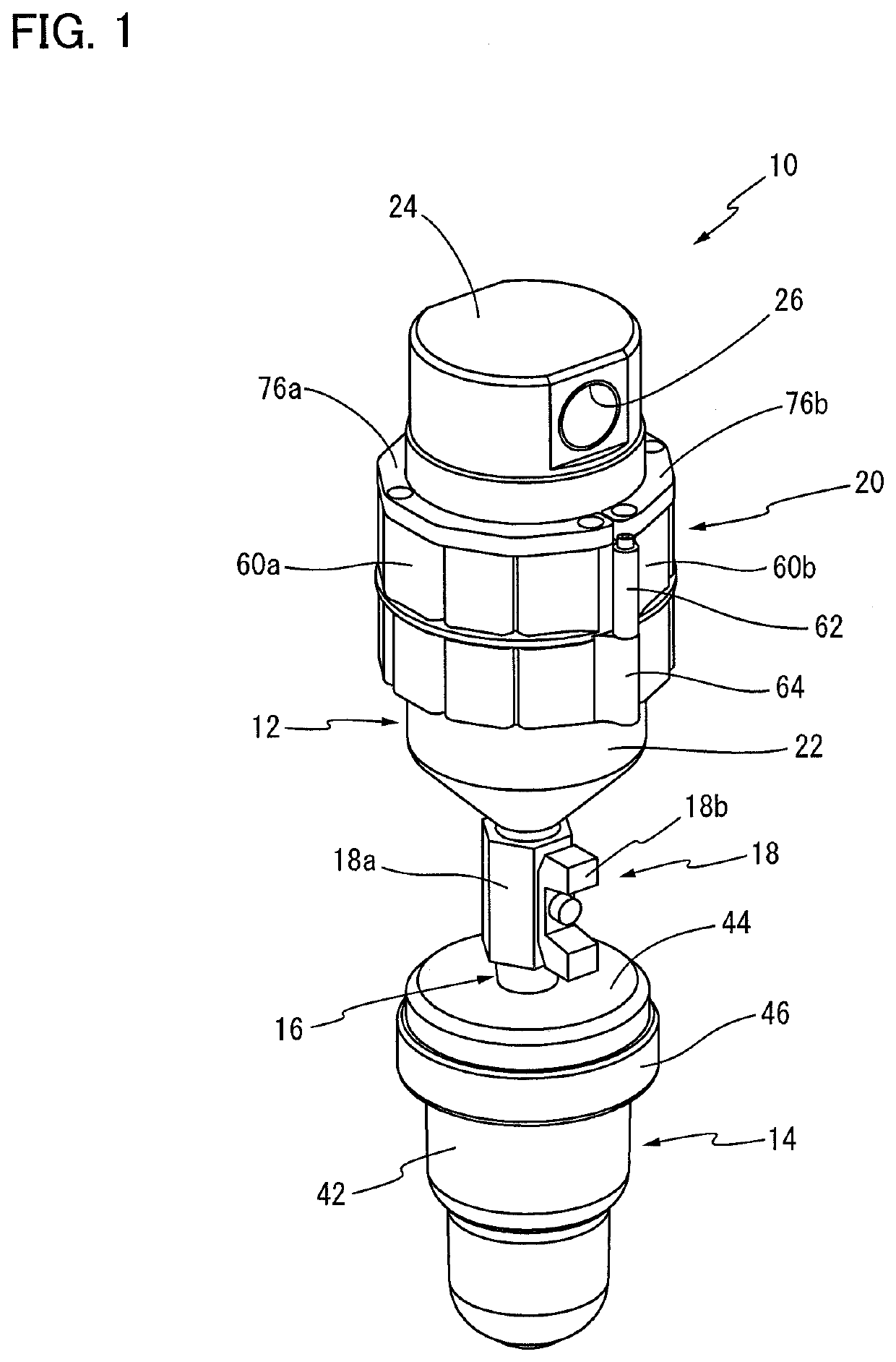
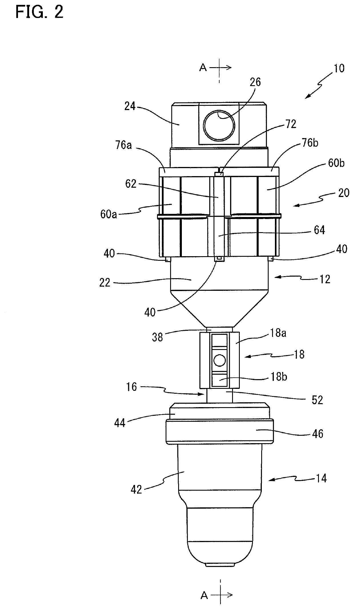
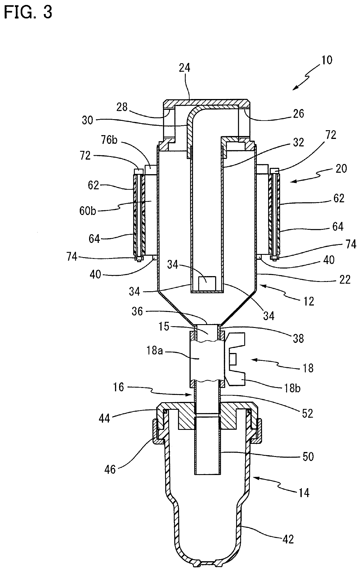
[0039]Referring first to the perspective view of FIG. 1, there is shown a magnetic filtration apparatus installed in the midway of a piping of a hydraulic system, in which inside a hydraulic oil circulates to activate a given actuator, as one embodiment of the magnetic filtration apparatus having a structure according to this invention. FIG. 2 is a front view of the magnetic filtration apparatus, and FIG. 3 is a cross sectional view taken along a line A-A of the form shown in FIG. 2. As is seen from the figures, a magnetic filtration apparatus 10 of this embodiment comprises: a cylindrical treatment container 12; a collecting container 14 positioned below the treatment container 12; a connecting part 16 for connecting the treatment container 12 and the collecting container 14, with a communication passage (15) installed in its...


PUM

PropertyMeasurementUnit
opening angleaaaaaaaaaa
magnetic fieldaaaaaaaaaa
gravityaaaaaaaaaa

Abstract

Provided is a magnetic filtration apparatus with a simple structure for permitting easy and effective discharge of magnetic substances from the inside of a flow passage to its outside, the magnetic substances being captured by attraction from a liquid to be treated by magnetic separation. The magnetic filtration apparatus includes a treatment container 12 having an inlet 26 and outlet 28 of the liquid, and a discharge port 36 of the separated magnetic substances. A magnetic apparatus 20 attached around the treatment container 12 attracts the separated magnetic substances to an inner wall of the treatment container 12, while cancellation of the effect of the magnetic field generated by the magnetic apparatus 20 allows the attracted magnetic apparatus to flow into a detachable collecting container 14 positioned below the treatment container 12, due to the gravity, through a communication passage 15.

Description

CROSS REFERENCE TO RELATED APPLICATION[0001]This application is a continuation of the International Application No. PCT / JP2019 / 014927 filed on Apr. 4, 2019, which claims the benefit under 35 U.S.C. § 119(a)-(d) of Japanese Application No. 2018-160738 filed on Aug. 29, 2018, the entireties of which are incorporated herein by reference.BACKGROUND OF THE INVENTIONField of the Invention[0002]The present invention relates to a magnetic filtration apparatus. In particular, the invention relates to an improved structure of a magnetic filtration apparatus for attracting and separating magnetic substances from a liquid which is contaminated with the magnetic substances such as ferromagnetic particulates, by utilizing magnetic force.Description of Related Art[0003]Known devices and equipment with a structure in which a liquid such as a lubricating oil and a hydraulic oil circulates within their inside, including an engine, a transmission and various hydraulic systems, have been employed for v...

Claims


Application Information

Patent Timeline
Patent Type & Authority Applications(United States)
IPC IPC(8): B01D35/06B01D29/00B01D12/00B03C1/32
CPCB01D12/00B01D29/009B01D35/06B03C1/32B03C2201/18B03C1/288B03C2201/28B03C1/0332Y02P70/10B01D29/88
Inventor MAEDA, TATSUHIRO
Owner MAEDA SHELL SERVICES CO LTD
Why Eureka
Try Eureka