Expander for expanding metal pipes

Inactive Publication Date: 2020-05-21
CEBI HI TECH
View PDF0 Cites 0 Cited by
  • Summary
  • Abstract
  • Description
  • Claims
  • Application Information

AI Technical Summary

Benefits of technology

The present invention aims to improve the accuracy and precision of expanders, ensuring maximum expansion in both the push and pull modes. This is achieved by ensuring a correct and constant movement of the mandrel head, resulting in a highly precise desired expansion dimension.

Problems solved by technology

In the expanders thus formed, there may be a problem related to the conformation of the helical spring of the flexible rods, which does not ensure a correct and constant movement of the mandrel head and thus the desired expansion dimension.

Method used


Image

  • Expander for expanding metal pipes
  • Expander for expanding metal pipes
  • Expander for expanding metal pipes

Examples


Embodiment Construction

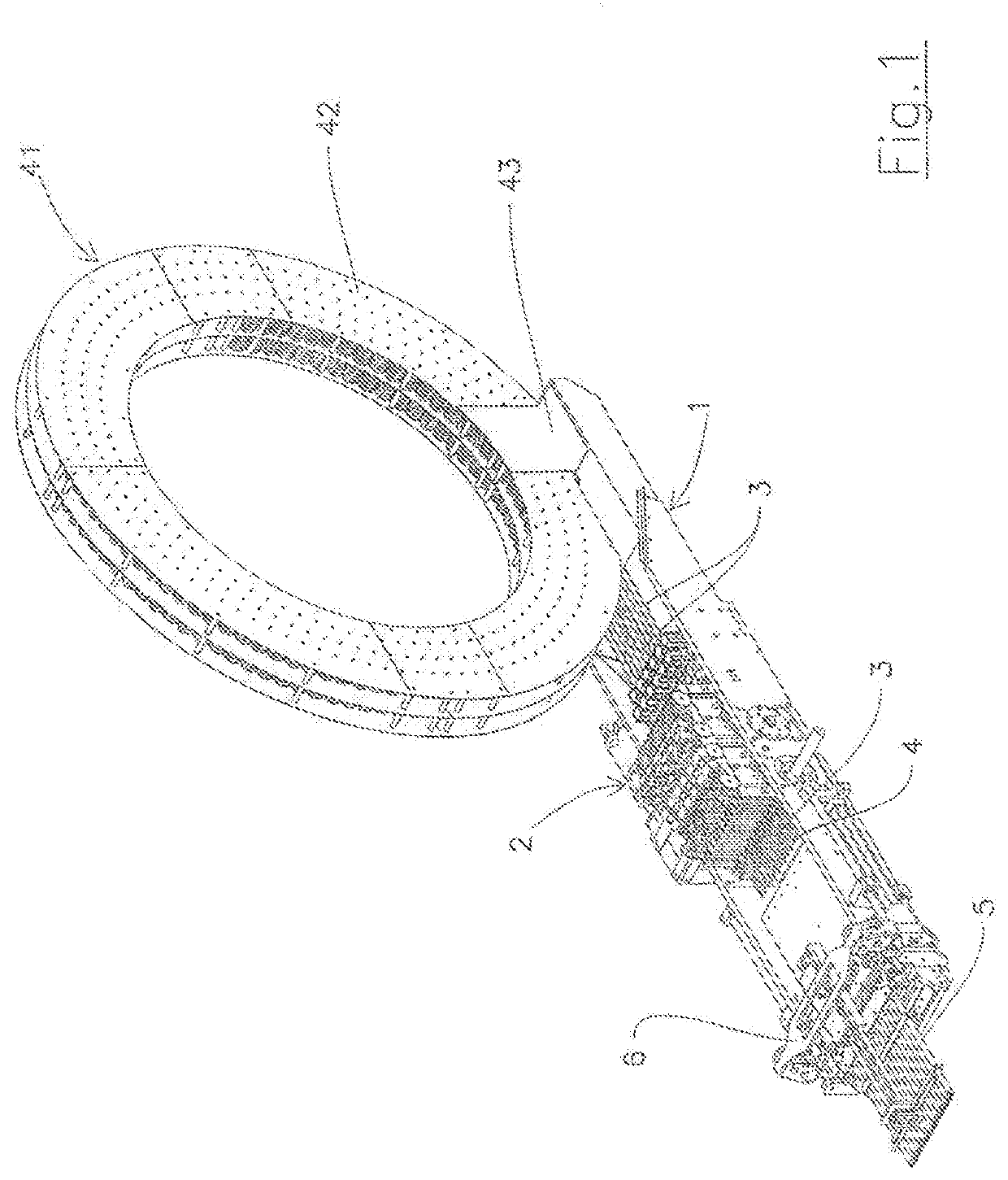
[0032]The expander shown as a whole in FIG. 1 comprises a supporting frame 1 which supports a moving assembly 2 of flexible rods 3 from which expander mandrels 4 extend, which can be inserted into the axial cavities of the respective pipes 5 the transversal expansion of which is desired. The aforesaid pipes 5 are kept in position aligned with the expander mandrels 4 by a support 6 fixed to a front end of the frame 1.

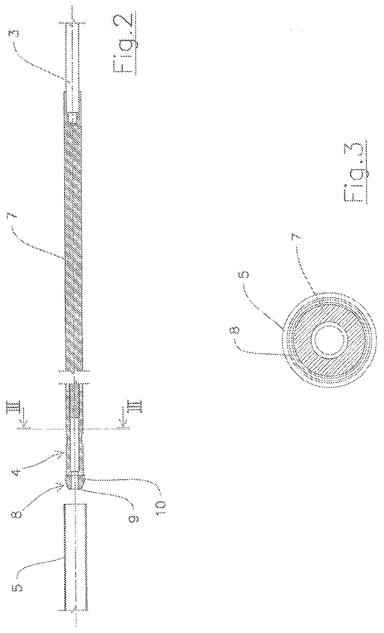
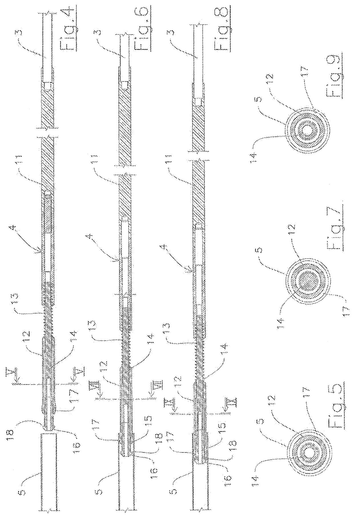
[0033]The expander mandrels 4 can be of two types, shown in FIGS. 2-3 and 4-9, respectively.

[0034]The expander mandrel in FIGS. 2-3 is of the push type, i.e. is able to operate the transverse expansion of pipe 5 by means of axial pushing. For such a purpose, the mandrel comprises a rigid body 7 with a rear end fixed to the front end of a respective flexible rod 3 and a front end ending in a substantially truncated-cone-shaped expansion head 8 with a terminal front 9 of diameter smaller than that of the inner cavity of pipe 5 and a section 10 behind of a larger diameter t...


PUM

PropertyMeasurementUnit
Lengthaaaaaaaaaa
Flexibilityaaaaaaaaaa

Abstract

An improved expander for expanding metal pipes comprises a plurality of flexible rods (3), which are fed in parallel manner towards a corresponding plurality of parallel pipes (5) to axially insert respective expander mandrels (4) placed at the front end of the flexible rods (3) therein. The aforesaid flexible rods (3) are made in form of a harmonic steel stem with round section and smooth outer surface.

Description

BACKGROUND OF THE INVENTION[0001]The present invention relates to an improved expander for expanding metal pipes.[0002]The term “expander” means a machine capable of performing transversal expansion or widening of the inner space of metal pipes used for various purposes, particularly but not exclusively for supplying refrigerant or heating fluid inside the fins of finned pack heat exchangers.[0003]An expander of this type is described in Italian patent No. 1426936 by the Applicant and comprises a plurality of flexible rods, which are fed in parallel towards a corresponding plurality of parallel pipes to axially engage therein the respective expander mandrels placed at the front end of the flexible rods.[0004]The flexible rods consist of a metal wire spring wound in a cylindrical helix in which a braided steel wire cord axially extends, the front end of which is fixed to the rear end of the expander mandrel.[0005]There may be two types of expander mandrels, one capable of expanding t...

Claims


Application Information

Patent Timeline
IPC IPC(8): B21D41/02
CPCB21D41/026B21D39/20B21D53/085
Inventor CERLIANI, DANIELE
Owner CEBI HI TECH
Why Eureka
Try Eureka