Actively dampened centerless grinding process

a centerless grinding and active damping technology, applied in the field of grinding parts, can solve the problems of increasing the force of the grinding process, requiring bulky actuators, and constant vibration of the machine, so as to improve the grinding precision

Pending Publication Date: 2020-05-21
IDEKO SCOOP
View PDF6 Cites 3 Cited by
  • Summary
  • Abstract
  • Description
  • Claims
  • Application Information

AI Technical Summary

Benefits of technology

[0023]The occurrence of vibrations is thereby detected during grinding, and by means of the inertial actuator, the moving mass of the actuator which is arranged in the head can be accelerated such that the force required for damping the vibrations is introduced. The vibrations produced in the grinding machine during grinding of the part are thereby attenuated or eliminated in real time and in an efficient manner.
[0028]Detection means and an inertial actuator which are arranged in a co-located manner are therefore used, thus making the attenuation of the vibrations produced in the machine more effective. This co-located distribution in which the detection means and the inertial actuators are located at one and the same point is recommended because this way all the vibration modes existing in the bandwidth of the inertial actuator may be attenuated in theory. In the case of a non-co-located distribution, like in the case of document JP2005199410A, vibration control may be hindered when there are vibration modes with different phase between the measurement point and the actuation point within the bandwidth of the actuator.
[0032]Preferably, the control strategy used by the invention is based on measuring the speed of the vibrations due to grinding, preferably measurements in the head, and applying by means of the inertial actuator a force proportional to the amplitude of that speed, with the same frequency, but with the opposite phase. By introducing the damping force this way, damping proportional to the amplitude of the introduced force which allows increasing the dynamic rigidity of the machine is introduced.
[0037]According to the foregoing, a process for grinding parts in a centerless grinding machine, which allows improving grinding precision by attenuating vibrations originated in the machine due to the grinding process itself, is obtained.

Problems solved by technology

However, in centerless grinding, which is a variant of general grinding, these constant vibrations of the machine take a back seat in terms of importance, because centerless grinding is used for surface working operations and not only for finishing operations.
Furthermore, in centerless grinding, the width of the wheel used tends to be significantly greater compared to general grinding processes, thereby causing the forces of the grinding process to increase considerably.
The drawback of this is that the suspended mass must have a quantifiable value with respect to the modal mass of the vibration, and a bulky actuator which would take up a lot of space in the machine is therefore required.
Furthermore, the passive actuator would only work for a specific vibration mode and would not adapt to other different vibration modes that may appear, making it an unsuitable solution for damping process vibrations in a centerless grinding machine, given that the vibration frequencies in machines of this type can vary according to the cutting conditions.
However, with this arrangement, the actuator must provide rigidity at all times, so in the event that the actuator fails, the machine would no longer be able to work in a suitable manner.
However, the precise knowledge of the vibration is impossible when the vibrations originate from the grinding process, and therefore cancellation cannot be used for attenuating vibrations of this type.
Furthermore, the use of this control strategy for eliminating the constant vibrations in machine, such as the imbalance in the wheel, may even lead to the case where the vibrations due to the cutting process are amplified as the cancellation may cause the excitation of these other vibration modes (see JP2002254303A).

Method used


Image

  • Actively dampened centerless grinding process
  • Actively dampened centerless grinding process
  • Actively dampened centerless grinding process

Examples


Embodiment Construction

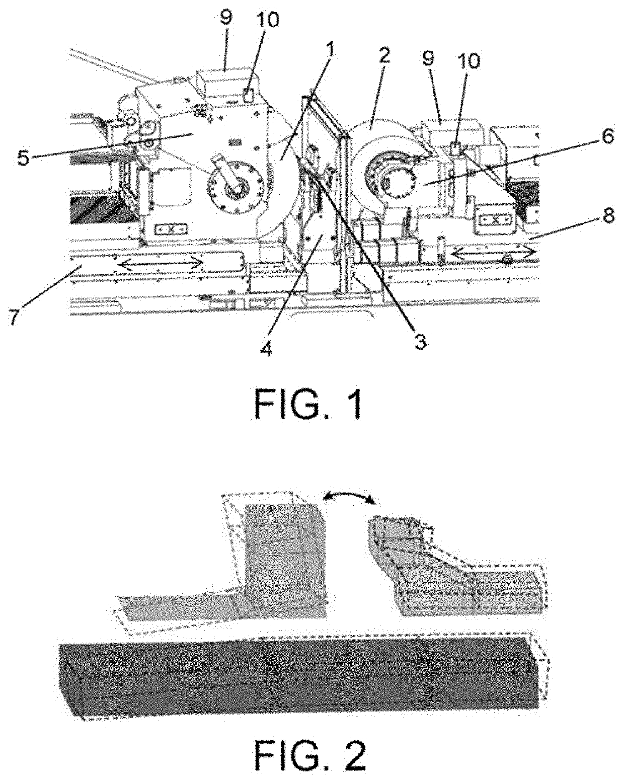
[0044]FIG. 1 shows an example of a centerless grinding machine in which the grinding process of the invention can be applied. The grinding machine comprises two wheels (1, 2), a grinding wheel (1) and a regulating wheel (2), between which there is arranged a part (3) to be ground supported on holding means (4). Each wheel (1, 2) is arranged in a head (5, 6) and each head (5, 6) is arranged on translation means (8, 9).

[0045]The machine configuration depicted in FIG. 1 is not limiting for the invention, where it is obvious for one skilled in the art that the grinding process may be applied in centerless grinding machines with a different machine configuration.

[0046]By means of the movement of the heads (5, 6), the wheels (1, 2) move closer to / farther away from one another in a direction perpendicular to the part (3). Therefore, in operation, the wheels (1, 2) apply pressure on the part (3) in the direction in which the wheels (1, 2) move closer to one another, such that the part (3) i...


PUM


Abstract

The present invention relates to an actively dampened centerless grinding process for a centerless grinding machine having wheels, between which there is arranged a part to be ground, and heads carrying the wheels, which process has moving the wheels closer to one another by applying pressure on the part for the grinding thereof, such that vibrations are generated in the grinding machine due to grinding, measuring the vibrations due to grinding, and introducing, depending on the measurement, an active damping force (Fact) parallel to the force flow of the grinding machine and by means of using an inertial actuator acting directly on one of the heads, such that the vibrations due to grinding are attenuated.

Description

CROSS-REFERENCE TO RELATED APPLICATION[0001]This application claims the benefit of priority from European Patent Application No. 18382825.0, filed Nov. 19, 2018, which is incorporated herein by reference.FIELD OF THE ART[0002]The present invention relates to a process for grinding a part in a centerless grinding machine. The proposed process uses a control strategy which, by means of an inertial actuator, allows introducing an active damping force which attenuates vibrations produced due to the grinding process itself, thereby improving the precision of the centerless grinding machine.STATE OF THE ART[0003]Grinding is a widely used process to perform abrasive machining operations with greater dimensional precision and a lower degree of roughness compared to a stock-removal machining operation. Mainly due to this reason, grinding is treated as a finishing process, in which the forces of the grinding process are not too large.[0004]In that sense, general grinding focuses essentially o...

Claims


Application Information

Patent Timeline
Patent Type & Authority Applications(United States)
IPC IPC(8): B24B41/00B23Q11/00B23Q1/60B23Q15/12B24B5/18B24B41/02G05B19/404
CPCB23Q11/0032B24B41/007G05B2219/37434B24B5/18B23Q1/60G05B19/404G05B2219/41256B24B41/02B23Q15/12G05B2219/45145B24B49/00B24B5/22
Inventor ASTARLOA BADIOLA, ASIEREZENARRO LETE, ITSASO
Owner IDEKO SCOOP
Why Eureka
Try Eureka