
Signal cancelling transmit/receive multi-loop antenna for a radio frequency identification reader

a radio frequency identification and transmit/receive technology, applied in loop antennas, instruments, indirect connection of subscribers, etc., can solve the problems of reducing the operating range of tags, affecting the efficacy of rfid systems, and affecting the sensitivity of readers, so as to maintain the sensitivity of close-by identification tags, minimize interference, and minimize reader sensitivity

Active Publication Date: 2011-09-01
ALLFLEX USA
View PDF54 Cites 20 Cited by
  • Summary
  • Abstract
  • Description
  • Claims
  • Application Information

AI Technical Summary

Benefits of technology

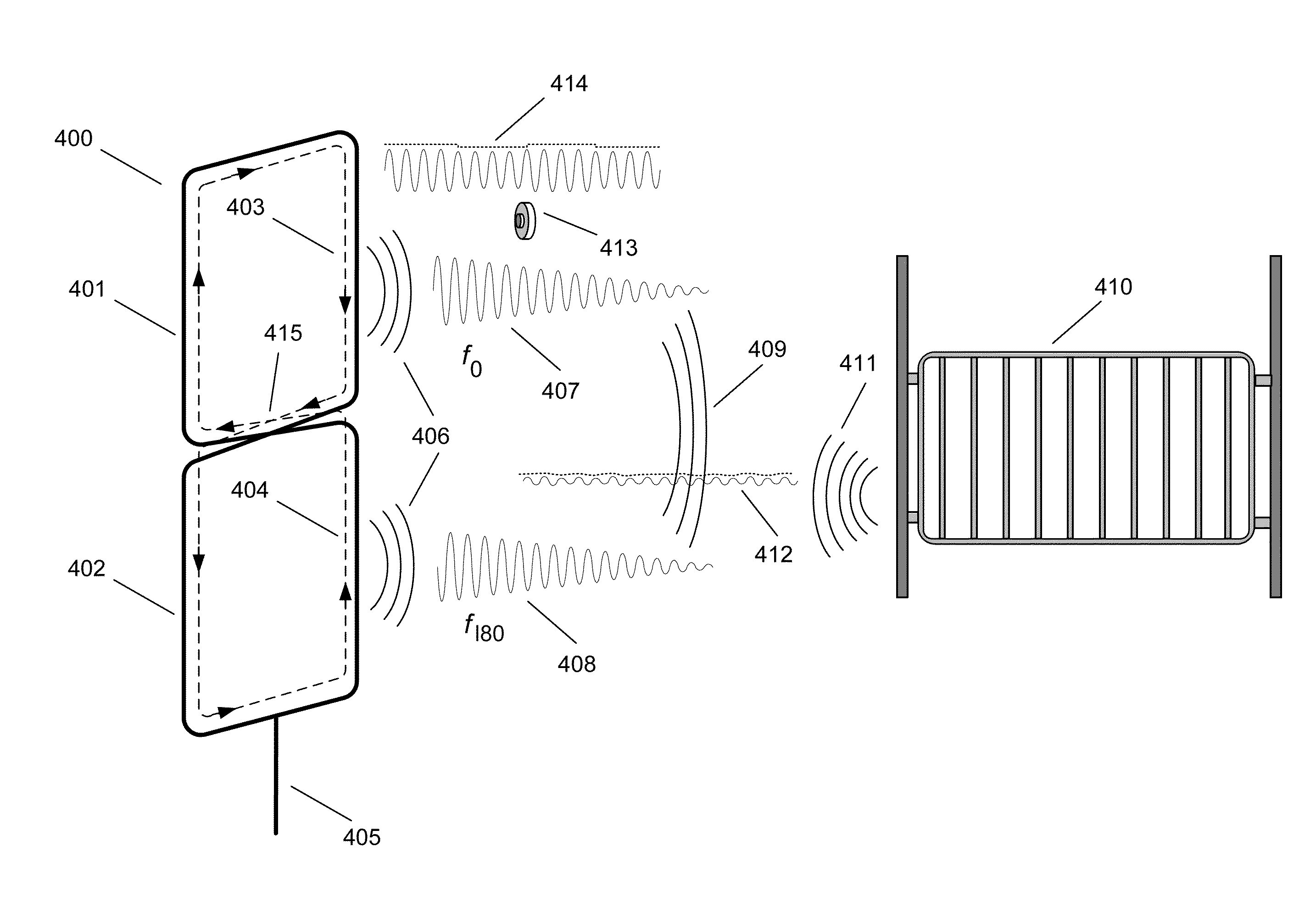
[0021]Systems and methods in accordance with embodiments of the invention read RFID transponders and exclude electromagnetic noise related to the vibration of metal objects at acoustic frequencies using multi-loop signal cancelling antennas. Accordingly, an objective of the invention is to use signal cancelling antennas to limit the spatial penetration of the antenna's magnetic field beyond the vicinity occupied by the tag, and minimize the reader's sensitivity to distant magnetic field perturbations, while maintaining sensitivity to the close-by identification tag. In contrast to many prior art multi-loop noise cancelling antennas that utilize separate transmit and receive antennas, noise cancelling antennas in accordance with embodiments of the invention can use a single multi-loop antenna for transmit and receive functions. Furthermore, multi-loop signal cancelling antennas in accordance with embodiments of the invention also transmit a single frequency tag activation signal, sense a multiple bit tag signal containing a unique binary identification sequence, and minimize interfering noise associated with proximal acoustically resonating metallic structures, by limiting the spatial penetration of the antenna's magnetic field and by minimizing the antenna's sensitivity to distant passive magnetic field perturbations. Noise interference from nearby resonating metallic structures is thereby significantly attenuated and / or eliminated through bilateral signal cancellation. In several embodiments, RFID systems also utilize an alternate antenna orientation that optimizes detection of identification tags characterized by random physical orientation.
[0022]One embodiment includes a signal cancelling antenna, and an RFID reader circuit configured to drive the signal cancelling antenna with an interrogation signal In addition, the RFID reader circuit and the signal cancelling antenna are configured to detect data modulated onto the interrogation signal, the signal cancelling antenna includes a plurality of loops and at least two of the plurality of loops generate magnetic fields having opposite polarity when driven by the interrogation signal, the plurality of loops are physically arranged so that, when driven by the interrogation signal, the magnetic field proximal to each loop activates any passive RFID transponders present, and the physical arrangement of the plurality of loops causes the magnetic fields generated by the loops, when driven by the interrogation signal, to collectively cancel with increasing distance from the antenna.

Problems solved by technology

RFID systems, such as systems compliant with ISO 11785, are based on radio frequencies (RF), and are susceptible to electromagnetic interference in the same way that radio communications, such as AM and FM broadcast radio and TV, are affected.
Radio frequency interference can disrupt the efficacy of RFID systems by reducing the operating range of tags, and in extreme cases rendering the system inoperative.
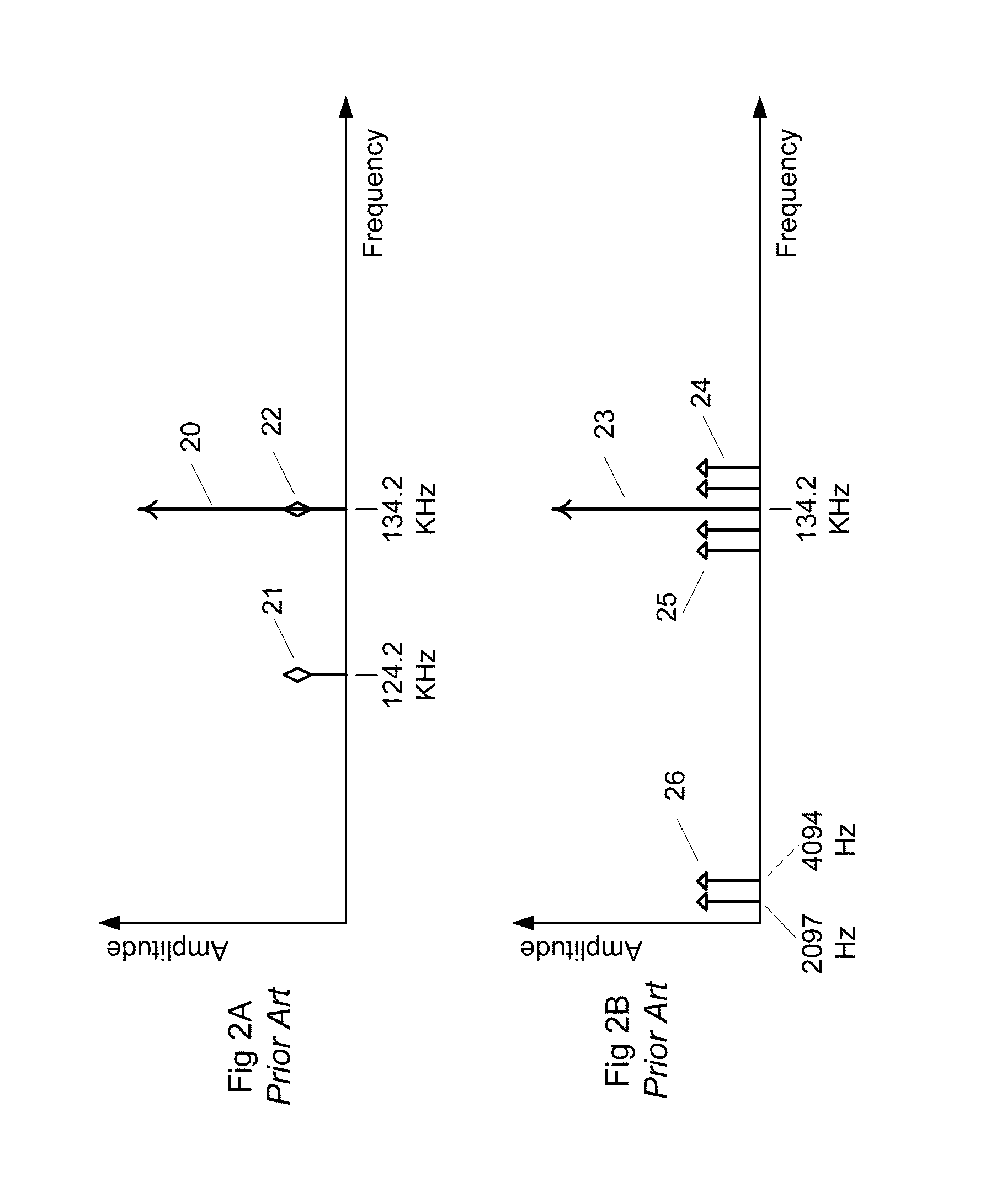
FDX-B tags, however, can be affected by electrostatic discharge, reader power supply noise, and RF signals containing FDX-B data frequency amplitude modulation.
Both HDX and FDX-B are equally disrupted by AC motor variable frequency drive controllers, which tend to radiate wideband amplitude and frequency modulated RF.
In some situations, nearby metallic structures resonate due to machinery vibration and shock.
Animal movement can also induce acoustic noise resulting from the impact and vibration of metallic structures that comprise gates, corrals, stanchions, traders, and the like.
Such low read rates are generally unacceptable in commercial applications, where read rates in excess of 99% are desirable.
Emitted electromagnetic radiation can create interference among electronic devices that share the same spectrum.
Electromagnetic interference is especially problematic when the interfering frequencies coincide with the frequencies used by a particular radio frequency system, and separating the desired signal from the interfering signal can be particularly difficult.

Method used


Image

  • Signal cancelling transmit/receive multi-loop antenna for a radio frequency identification reader
  • Signal cancelling transmit/receive multi-loop antenna for a radio frequency identification reader
  • Signal cancelling transmit/receive multi-loop antenna for a radio frequency identification reader

Examples


Embodiment Construction

[0058]Turning now to the drawings, RFID readers including multi-loop signal cancelling antennas configured to read RFID transponders and exclude electromagnetic noise related to the vibration of metal objects at acoustic frequencies in accordance with embodiments of the invention are illustrated. In many embodiments, the loops of the signal cancelling antenna generate magnetic fields that have instantaneous opposite polarity and effectively cancel when they merge a distance from the antenna. Antennas in accordance with embodiments of the invention are referred to as signal cancelling, as opposed to noise cancelling, because the antennas generate magnetic fields that effectively cancel the interrogation signal (i.e. the signal generated by the antenna) a distance from the antenna that is typically a small multiple of the largest dimension of the antenna. The effect of cancelling the interrogation signal beyond a certain distance from the antenna is to eliminate interference from acou...


PUM


Abstract

In an inductively coupled radio frequency identification (RFID) system deployed in animal and livestock applications, reading system efficacy can be compromised by animal movement on, around, or near metal structures prone to producing sonic frequencies. Such is the case, for example, when a walk-by antenna is mounted at the entry door of a livestock transport trader, and animals transit on a metallic ramp and metallic trader floor. Associated with the observable acoustic noise are subtle disturbances in the magnetic field surrounding the antenna due to vibrating metal altering the reluctance of the antenna's magnetic field. This acoustic noise manifests itself as an electrical noise phenomenon that interferes with the signals of certain types of identification tags which rely on amplitude modulation. The detrimental effects of acoustic noise from metal structures can be mitigated by using a multi-loop antenna that limits the spatial distribution of the transmitted magnetic field and cancels close by magnetic field disturbances.

Description

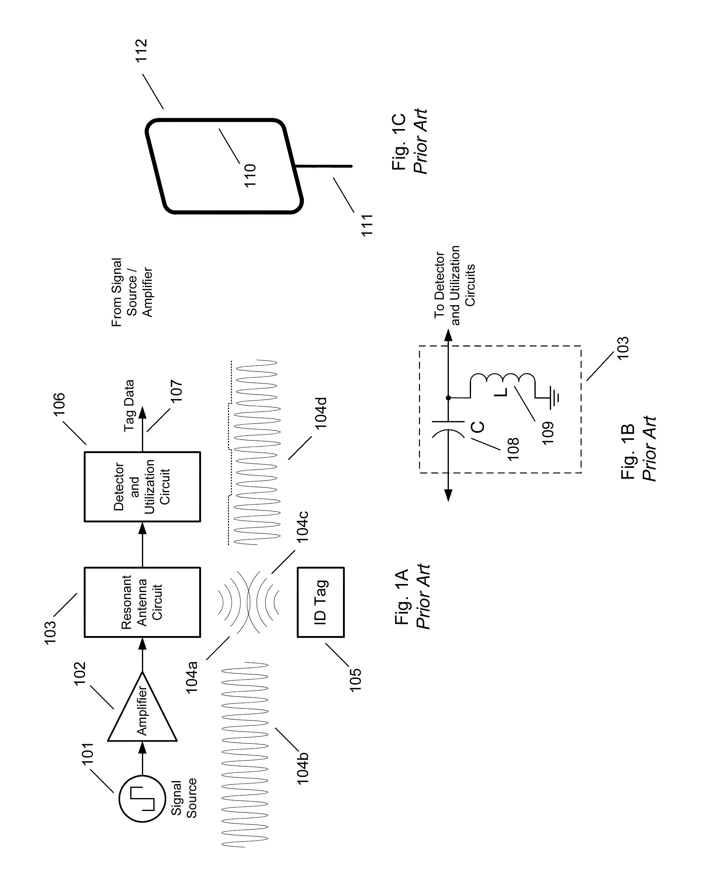
CROSS-REFERENCE TO RELATED APPLICATIONS[0001]The current application claims priority to U.S. Provisional Application No. 61 / 257,906, filed Nov. 4, 2009, the disclosure of which is incorporated herein by reference.FIELD OF THE INVENTION[0002]This invention relates to radio frequency identification (RFID) systems that use low frequency inductively coupled signals, and in particular, to noise cancelling antenna systems for use in RFID systems.BACKGROUND OF THE INVENTION[0003]Passive low frequency RFID readers and tags use operating principles that are well-known to those of ordinary skill in the art, and that are described in extensive detail in several seminal inventions, including U.S. Pat. No. 1,744,036 to Brard (1930), U.S. Pat. No. 3,299,424 to Vinding (1967), U.S. Pat. No. 3,713,146 to Cardullo (1973), and U.S. Pat. No. 5,053,774 to Schuermann (1991), and in textbooks such as “RFID Handbook” (Finkenzeller—1999).[0004]In an inductively coupled RFID system, as depicted in FIG. 1A, ...

Claims


Application Information

Patent Timeline
Patent Type & Authority Applications(United States)
IPC IPC(8): H04Q5/22
CPCG06K7/0008G06K7/10346H01Q1/00H01Q1/2216H01Q7/00
Inventor STEWART, ROBERT
Owner ALLFLEX USA
Learn More